Hello infrastructure enthusiasts! I had a lot of fun back in August 2023 talking about South Pole Electrical Infrastructure. Since then, several people have asked me to detail other infrastructure systems.
I started this post while I was still at Pole, but I only finally got around to finishing it. Better late than never – enjoy!
Overview
This post will focus on how we produce fresh water and how we dispose of wastewater at the South Pole.
The majority of the world’s population lives in coastal regions, and researchers in Antarctica are no exception.
Most Antarctic research stations sit on or near the coast. Coastal stations are easier to operate, because the ocean provides a moderating effect on the climate, access to ship-based transportation, a water source, and a mechanism to dispose of (hopefully treated!) wastewater.
In addition, many of the interesting scientific sites are located near the coast. The majority of human activity in Antarctica is for scientific research purposes, so it makes sense to situate these stations nearby the sites that they are designed to help study.
In fact, there are only three year-round stations that are not located on the coast. Here’s a decent map of major Antarctic research facilities, from COMNAP (The Council of Managers of National Antarctic Programs). Yellow dots are year-round facilities, red dots are summer-only facilities.

This is not an exhaustive map. I’m aware of stations that are not shown here. This is a decent estimation showing the general pattern of human activity in Antarctica. If your station isn’t shown here, please do not get mad at me. Take it up with CONMAP.
The South Pole is one of those three inland yellow dots, far from the coast. We’re located high up on an inland plateau, about 975 miles South of McMurdo Station. (Of course, we are, by definition, South of literally everywhere.)
Remember, McMurdo is the United States’ main coastal logistics hub for Antarctic research, and it’s where I spent the first 4 months after my arrival on-continent.
In this post, I’ll quickly review McMurdo’s water infrastructure, before moving on to discuss water infrastructure at the South Pole.
- McMurdo Freshwater Infrastructure
- McMurdo Wastewater Infrastructure
- South Pole Freshwater Infrastructure
- South Pole Wastewater Infrastructure
- Conclusion
McMurdo Freshwater Infrastructure
In order to appreciate the unique challenges of water management infrastructure at the inland South Pole Station, it’s worth taking some time first to understand water infrastructure at McMurdo, right on the coast.
As a coastal station, McMurdo has year-round access to liquid seawater, right at the bottom of the hill, at the edge of town. Sometimes it’s buried under ice, but there’s always liquid water available below that, even in the middle of winter when the air temperature is a brisk -30°F.
McMurdo brings in raw seawater using a series of pumps. The raw seawater intake infrastructure is located in building 179, the Seawater Intake Facility:

The seawater is pumped up a series of insulated pipes:

To safely transport water without it freezing in the pipes, we use thick, insulated pipes, with integrated heat trace cabling. Heat trace cabling is just controlled, high-resistance wiring that runs the length of the pipe. When electricity is passed through the wire, it heats up. The heat is trapped by the thick insulation, and it keeps the water in the pipe from freezing. This allows us to safely use above-ground pipes in -30°F weather:

Seawater is used for two purposes in McMurdo. The first use of seawater is for the salt water aquarium in Crary Lab:


The second use for seawater, is, of course, to produce potable (“domestic”) water for station operations.
At McMurdo, seawater passes through several major steps. I’ll be brief here, because the real focus of this post is the South Pole. All of this processing takes place at the McMurdo water treatment plant:
The first step is heating. Liquid seawater enters the plant at about 28°F. Since the water is salty, it remains liquid at a lower temperature than fresh water. Before we can remove the salt, we have to heat it. We use waste heat from the power plant to heat the water to about 37°F.
The second step is filtering. Raw seawater can contain sediment, which must be removed prior to further treatment.
The third step is desalination. McMurdo uses a reverse osmosis system for this. In short – the seawater is pressurized, then forced through a fine membrane. This process allows only pure water through. Salt, along with several other naturally-occurring minerals, are left behind. These are returned to the sea.
The fourth step is “polishing”. Pure water, straight out of the reverse osmosis system, isn’t actually desirable. It can cause issues with distribution piping, and it is less than ideal for human consumption due to both aesthetic (taste) and nutritional reasons. Polishing involves the use of chemicals to adjust the hardness and pH levels, for optimal distribution. A small amount of chlorine is also added, which helps mitigate the negative effects of any contamination in the storage and distribution system.
Finally, the water is sent to storage and distribution! McMurdo stores hundreds of thousands of gallons of treated water, ready for distribution. Remember, peak summer population can exceed 1,000 people. Water is also used for firefighting, so a significant amount of storage is required.

McMurdo Wastewater Infrastructure
Lucky you! I wrote a whole post about this last year, back in October 2022.
Check it out here.

That’s McMurdo! It’s not that weird. Cold, but not too cold. Take raw seawater, keep it from freezing, purify it, distribute it, use it. Take the wastewater, treat it, release it. Again, not that weird.
Now – let’s talk about water at the South Pole.
South Pole Freshwater Infrastructure
At the South Pole, there is no liquid water source available. Pole is hundreds of miles from the coast, high up on an inland plateau, and it’s absurdly cold.

Luckily – that plateau is made up of several thousand feet of snow! It’s a lot of work, but we can melt this snow and produce potable water.
This is no small feat of engineering, and the underlying physics means it’s an energy-intensive process. The deep-down snow at the South Pole is around -60°F. It takes 2.44 watt-hours (8.33 BTUs) of heat input to raise the temperature of 1 gallon of water by 1°F. Heating the equivalent of 1 gallon of water from -60°F to a reasonable liquid distribution temperature (50°F) means heating it up by a whopping 110°F.
That’s 268 618 watt-hours of raw energy
required just to bring a single gallon of water up to distribution temperature! edit: someone on the Internet
explained to me what “latent heat of fusion” was. This adds an additional 350 watt-hours for the
solid to liquid phase change, on top of the 268 watt-hours required for the temperature increase. Thanks!
This is one of the reasons we’re restricted to two-minute showers.
Supply
Water at the South Pole begins with a “Rodwell”, short for “Rodriguez Well”. The original design for the Rodwell comes from an engineer named Raul Rodriguez, who designed it for a camp in Greenland.
The Rodwell is located below the Rodwell support building, which is located several hundred feet away from station. By “The Rodwell”, I should clarify that I’m referring to the current Rodwell. As I’ll discuss later, these don’t last forever. We’re on what is now officially called “Rodwell 3”. We’ve had more Rodwells than that in the history of the South Pole, but the naming convention began when Rodwell location planning was standardized. We have locations already planned out for several more Rodwells.

The basic operation of a Rodwell is straightforward. You drill a hole in the snow. You start pumping hot water into the hole. The hot water melts the snow, which pushes outward and forms an underground lake. You can pump liquid water out of the lake! As long as you keep adding heat, by recirculating hot water down into the hole, you can keep expanding the lake and keep pumping water out of it.

Inside the support building is all the equipment we need to manage the Rodwell. The building is heated, and it contains control and monitoring equipment.

The well itself goes down several hundred feet. There’s two water lines, one for the water we pump out, and another for the hot water we recirculate down. There is also electrical wiring for the submerged pump, and signal wiring for sensors and control circuitry.
Normally, water is pumped out of the Rodwell, and then pumped hundreds of feet toward station, to the main water treatment plant. Some of the water is taken for station use. The rest of the water passes through a series of heat exchangers in the water plant, before it is then pumped back to the Rodwell. This heated, recirculated water is used to keep the underground lake serviceable.

Since the Rodwell is located several hundred feet from the water plant, we need backup systems to ensure that there is always a hot water supply to the Rodwell, even if something happened to the return piping between the water plant and Rodwell.
For resiliency, the Rodwell support building itself has backup boilers and heat exchangers. It’s essential that we never lose the recirculated hot water loop down into the Rodwell, else we risk damaging it. Constant heat input to the system is a critical requirement for its continued operation.

We use each Rodwell for several years. Once it gets too big (we’re talking millions of gallons), we stop pumping fresh water out of it, and we start over with a new one in a new location. The old one gets converted to be used for wastewater disposal – more on that part later.
Much more fascinating historical documentation about Rodwells can be found on Bill Spindler’s South Pole Station website.
As discussed above, once water is pumped out of the Rodwell, it exits the Rodwell support building, and it enters into the ice tunnels below.
The water then travels through pipes in the ice tunnels, en route to the main water plant. The ice tunnels are a network of subterranean utility corridors, carved directly out of the hard-packed snow. These tunnels sit deep below the station and its outbuildings.

Treatment
The water pipes exit the ice tunnels and enter the main water plant.
The water plant is located adjacent to the power plant, in the arches, at the bottom of the beer can. This means we can easily use a glycol loop carrying generator waste heat, from the power plant next door, to power these heat exchangers.

When the water enters the treatment plant, it first passes through a series of limestone contactors. Limestone contactors are used to increase the pH of the water by adding minerals. This improves corrosion resistance and makes the water suitable for human consumption. Contactors can be brought online or taken offline as needed, depending on the amount of treatment needed to achieve desired target outcomes.
Note that all water passes through the contactors, even water that will be recirculated back to the Rodwell.


After the limestone contactors, the majority of the water is sent toward heat exchangers, which are used to heat up the water that will be sent back to the Rodwell. The Rodwell circulation loop uses the majority of the water that is pumped out of the Rodwell. Only a small portion is diverted for domestic use.
The water is about 36°F when it is pumped out of the Rodwell, and it reaches about 42°F after it makes it all the way to the water plant and through the limestone contactors.
Domestic water does not receive any direct supplemental heating further along in the process. Additional heat gains are due to ambient heat absorption from the water treatment plant, or due to heating along the insulated, heat-traced piping.
Rodwell recirculation water, on the other hand, needs to be heated quite a bit, up to about 84°F. Remember, this water is pumped back down into the Rodwell, to maintain and expand the underground lake.
Here you can see the heat exchanger infrastructure. Hot glycol is pumped in from the power plant next door. The heat exchangers place the hot glycol loop and water loop in close proximity, separated only by small layers of thermally-conductive metal. This allows for the efficient transfer of heat without the contents actually touching.

The heat exchangers heat up the water to about 84°F. This heated water is sent back to the Rodwell building, where it is pumped back down into the Rodwell.
The remaining portion of the water is destined for domestic use. It receives additional treatment.
First, the water passes through a series of sediment and carbon filters:

Next, sodium carbonate (soda ash) is used for additional fine-grained pH control:

Finally, chlorine (calcium hypochlorite) is used as a disinfectant:
Once the domestic water has passed through all of these treatment steps, it is stored in bulk, unpressurized tanks. There are two tanks, so one can be taken offline for maintenance. The tanks are several thousand gallons, and they provide a storage buffer to guard against scheduled or unscheduled interruptions in the Rodwell supply or treatment process.

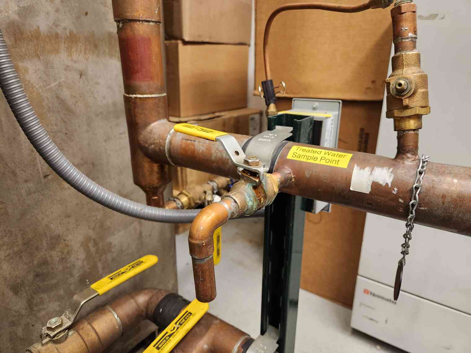
A treated water sample point is provided, to allow for scheduled checks of water quality, just prior to the water being pressurized for domestic supply:
Water quality is checked at several points throughout the treatment and distribution process. A lab table contains a variety of tools used for these measurements:

Distribution
The final step in the domestic water treatment process is to pressurize and store enough water to provide a reliable domestic supply:


Domestic water for the main elevated station must be carried from the tank here, up the beer can, and into the station. This is a vertical gain of about 50 feet, which must be factored into the pressure setpoint for the distribution system. These pipes are insulated, because the beer can is not heated.
The pipes exit the beer can and enter the elevated station, into the subfloor. The subfloor is a sort of crawl space located just below the 1st floor.
The elevated station contains one additional, pressurized tank at station level, for fire suppression. We have automatic fire sprinklers installed throughout the elevated station. Here you can see the large, pressurized fire suppression water tank:

Other than that, the water is used to serve fixtures throughout the station, just like you’d expect in a normal building!
Fixtures
The kitchen is one of the larger water consumers. Here you can see our dish pit. Winter staff take turns washing dishes, according to a posted schedule:
Here is an important permanently-installed water appliance – our espresso machine. This machine was critical to my morale during the long winter:

Laundry works much the same as it does back home.
Most of the washers are only connected to cold water, as an energy saving strategy. A few lucky (and coveted) machines have both a hot and cold water connection:
The only major difference in the laundry room is that our clothes dryers have direct glycol heat exchangers, instead of using electrical resistance heating:

Moving on – this is one of the South Pole bathrooms! We participate in weekly “house mouse” cleaning tasks – this week, it was my team’s turn to clean. Other cleaning tasks include mopping the halls, vacuuming carpeted spaces, and shoveling snow from outside station entrances.


Finally, completing our tour of domestic water fixtures, we have a genuine South Pole drinking fountain:

It’s an Elkay EZS8SF with the LK1110 glass filler add-on – an all-around solid choice for commercial drinking fountains.
And that pretty much covers the freshwater infrastructure at Pole!
South Pole Wastewater Infrastructure
Wastewater at Pole is handled much differently from wastewater at McMurdo!
As a reminder, from my McMurdo Wastewater Plant post, wastewater at McMurdo goes through a full wastewater treatment process. Treated wastewater is discharged into the ocean, and solids are processed and sent back to the United States for disposal.
At Pole, we use the old, spent Rodwells for storing wastewater. When a Rodwell has reached its maximum size, we stop drawing fresh water from it, and we convert it into wastewater storage. From then on, it is known as the “sewage outfall”.
Raw sewage and other wastewater flows into the current sewage outfall via a network of sewage pipes. The wastewater is stored underground indefinitely. No treatment is performed on this wastewater before it is sent underground. There are millions of gallons of raw, untreated wastewater stored in outfalls beneath South Pole Station.
As of this writing (June 2024), a wastewater treatment plant is not currently planned or budgeted for South Pole Station, although one has been discussed at various points throughout the history of South Pole Station. A wastewater treatment plant does appear as a recommendation in the South Pole Station Master Plan Draft 2024 (32 MB PDF) document on the NSF website.
Disposing of raw sewage by injecting it beneath the ice is permitted under the Antarctic Treaty System, which is codified in US law under 45 CFR § 671.12(f).
As I stated in my post about South Pole Electrical Infrastructure, it is my sincere hope that we continue working, with urgency, to reduce the environmental footprint of US Antarctic research.
Wastewater from the elevated station flows from domestic drains and collects in holding pits. There are two main holding pits in the elevated station.
The purpose of these is twofold: First, these pits provide a temporary storage buffer, allowing use of plumbing fixtures within the station during periods of maintenance on the discharge piping or sewer outfall.
Second, wastewater can be collected in these pits until they are full, and then the wastewater can be force discharged at a high flow rate. Discharging at a high flow rate allows for efficient and more complete carrying of suspended solids. If waste were discharged all the way to the sewer outfall at the rate it was produced, the system would suffer from blockages caused by solids that settled out in transit.
The first pit, for the “B” pod, is also co-located with our emergency water purification infrastructure, inside the Emergency Power Plant (EPP). This is part of the “lifeboat”, a wing of the station with redundant infrastructure that could function on its own in case the rest of the station were compromised.
Here you can see the wastewater holding pit, as well as some of the emergency water purification equipment.
This wastewater pit collects all wastewater via gravity from the “B” pod. It normally discharges to the main sewage/wastewater outfall. However, in the event that this was compromised, it can also discharge to a much smaller emergency outfall. This ensures continuity of wastewater disposal in the event of an issue with the primary wastewater outfall.
The emergency water purification infrastructure here can produce potable, domestic water by melting snow. A portable snowmelter can be set up just outside, with heat provided by a glycol loop.
Up next is the “A” pod wastewater pit. This one is located inside a large mechanical room on the 1st floor of the “A” pod. Wastewater collects here via gravity from all fixtures in the “A” pod. It also discharges to the main outfall.

Once the pits are full, they automatically discharge to the sewer outfall. This follows roughly the same path as the domestic water supply piping. The pipes exit the station, go down the beer can, and travel through the ice tunnels, until they reach the current sewer outfall.

Here you can see the piping entering the ice tunnels, off of the corridor at the base of the beer can:

Deep inside the ice tunnels, here is the current sewer outfall, showing the insulated pipes. This is the discharge point for all of South Pole Station’s wastewater, until we move to Rodwell 4 for freshwater, at which point Rodwell 3 will become the new sewer outfall.


Of course, not every building is connected to the plumbing system. In fact, at South Pole, only the elevated station and the power plant arch have running water and wastewater connections. The outbuildings (IceCube, MAPO, DSL, ARO, etc) are too far away, and so far it hasn’t been cost-effective to connect them.
For folks working outside away from station, there are a variety of options.
During the summer, when the population is high, we have porta-potties strategically located around campus:
Without a permanent sewer connection, waste from porta-potties must eventually be carried back to station once the porta-potties fill up.
Permanent outbuildings also often have an established solution for handling human waste from workers. These solutions range from simple buckets, to permanently-installed dry toilets with removable storage bins.
For work that takes you away from station, without access to toilet facilities, many personnel also carry portable bottles. These are a formal item, provided by USAP, and marked for their intended use. They are 32oz “HDPE” Nalgene bottles.
You can obtain one at the beginning of your season, and it’s your responsibility to return it, thoroughly cleaned and sanitized, before you depart. These are often used by personnel who travel to deep field locations, but they are also helpful for any situation where you may find yourself away from permanent facilities.
Conclusion
And there you have it – a brief tour of South Pole water and wastewater infrastructure!
Much like South Pole Electrical Infrastructure, the infrastructure that makes all this possible is generally hidden from view. From an average user’s perspective, living and working in the elevated station, everything functions pretty much the way you’d expect it to.
When you’re washing dishes in a windowless, heated room, and you turn on the faucet to fill the sink, it’s easy to forget all the work going on behind the scenes to make all this happen.
But venture out to the Rodwell in the middle of winter, when it’s negative 100°F, and you’ll quickly be reminded of the forces we’re up against.
From cold, to wind, to relentlessly accumulating snow, to the long, long supply chains for engineering expertise and spare parts, it’s a challenge to make things work at Pole. Our water and wastewater systems are critical infrastructure that enable humans to live at the bottom of the world.
Thank you everyone, again, for your patience! I wrote most of this post last winter while I was at Pole, and I appreciate all the words of support from folks who liked my past writing.
I hope everyone enjoyed reading this as much as I enjoyed writing it!
