
Our continued survival here at the South Pole, as temperatures dip below -100°F, is enabled by a series of primary, secondary, and tertiary systems for keeping the station warm, lights on, water flowing, communication links healthy, and food cooking.
In this post, I’m going to talk about the infrastructure for generating and distributing power at the South Pole. I won’t sugarcoat it – we burn a lot of fossil fuel here, and we burn plenty more in the supply chain along the way. It is my sincere hope that we continue working, with urgency, to reduce the environmental footprint of US Antarctic research, both point-of-use and in the supply chains along the way.
Before we get into the technical details of how things work at the South Pole, it’s worth taking a look at a few examples of alternative energy throughout Antarctic history.
Alternative Energy in Antarctica
Alternative energy solutions have been slow to reach Antarctica. There have been some poorly-executed attempts in the past, such as McMurdo’s ill-fated nuclear reactor (PM-3A, nicknamed “nukey poo”), which operated from 1962 through 1972. It was prematurely retired due to construction flaws, which resulted in contamination of the site and required extensive remediation. Photo from SouthPoleStation.com (despite the website name, this reactor was operated at McMurdo Station):
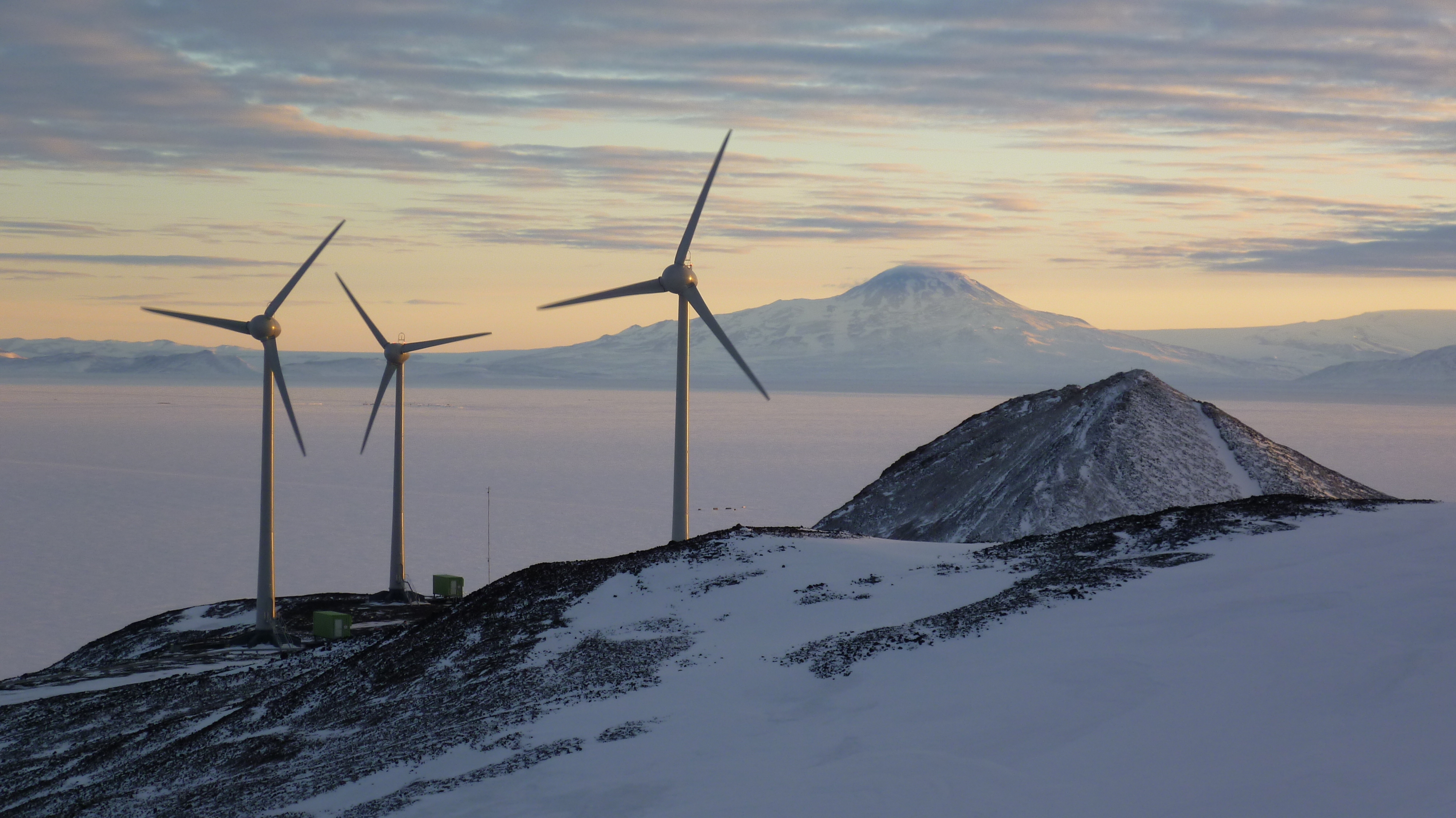
More recently – one of the largest examples is the Ross Island Wind Farm, which was originally constructed from 2008 through 2010. The project includes three wind turbines, as well as interconnection, conversion, and control systems. The project resulted in a coupling between McMurdo Station and Scott Base into a single electrical network. Conversion between NZ (50hz) and USA (60hz) electrical standards is done by a static frequency converter located at Scott Base.
Most importantly, this project incorporated approximately 1 megawatt of peak renewable capacity onto this newly-coupled grid, which increased the efficiency and resiliency of both stations’ operations. For a frame of reference, average McMurdo electrical demand ranges from 1 to 2 megawatts, depending on population, season, weather, and what projects are ongoing.
I found some wonderful notes about the Ross Island Wind Farm project in a US National Renewable Energy Laboratory (NREL) presentation, from 2012, here (1.2 MB PDF).
The Ross Island Wind Farm should be getting an upgrade soon, per the Scott Base Redevelopment website here.
South Pole Electrical Infrastructure
For the rest of this post, I’m going to focus on the as-built systems we have here at Pole. Remember that I am a first-year seasonal contractor working in IT, not utilities. I am a guest and a stranger in utility areas, and I’m doing my best to accurately represent systems about which I have no formal professional competence.
Furthermore, I am not going to focus on the wider implications or externalities of the technology choices we’ve made. These systems are part of a much larger operational, infrastructural, and political machine. I have no special insight into the United States Antarctic Program’s long-term energy strategy.
Now – let’s dig in!
Table of contents
- Overview
- Fuel Management
- Power Generation - Primary
- Power Generation - Emergency
- Electrical Distribution
- Conclusion
Overview
South Pole Station is a fairly large campus, encompassing a single elevated station, as well as several dozen outbuildings. Energy demands here are diverse and representative of a similarly-sized campus back home, though of course with increased heating load.
We use a small amount of gasoline (“mogas”) to power snowmobiles, light trucks, and portable power equipment. But besides that, energy at South Pole Station comes entirely from burning AN-8 fuel. We burn this in our primary power plant generators, as well as in boilers to heat outbuildings, and in heavy equipment used around campus.
We use generator waste heat directly to heat the station. We also use it to help maintain our water supply, which requires a steady supply of heat. June 2024 edit: I wrote a whole post about South Pole Water Infrastructure. Check it out!
We use generated electricity to run everything you need on a modern campus – pumps, compressors, blowers, heat trace cabling for plumbing, lights, an elevator, IT equipment, kitchen equipment, a sauna, science projects, and a variety of miscellaneous plug loads.
Fuel Management
Fuel at the South Pole is primarily AN-8, an aviation fuel blend that is formulated to remain liquid at low temperatures. This property is helpful, because it allows us to store it in bulk without constant heating. Our underground storage, in the fuel arch, stays in the -45° to -60° Fahrenheit range year-round. The formal “freeze point” of AN-8 is -72° Fahrenheit. The freeze point of AN-8’s closest mainstream formulation, known as JP-8, is -52° Fahrenheit.
For more information about AN-8 and the logistical considerations surrounding its use, check out this report (1.2 MB PDF), from the Engineer Research and Development Center (part of the US Army Corps of Engineers).
Transport via LC-130
The details of how we procure and deliver fuel to McMurdo is outside the scope of this post. The short version is: we get it delivered to McMurdo via fuel tanker ship. McMurdo can store several million gallons of fuel.
AN-8 is brought from McMurdo to Pole in one of two ways. The first is on LC-130s, the primary planes that move people and cargo to Pole. The LC-130s themselves burn AN-8. At McMurdo, if we fill the LC-130 fuel tanks beyond what is needed for the flight from McMurdo to Pole and back, we can offload the extra fuel at Pole.

This works well, but air transportation is… not great, from a fuel efficiency standpoint. According to an analysis done by ERDC, available here (750 KB PDF), an LC-130 burns about 1.33 pounds of fuel in order to transport one pound of fuel from McMurdo to Pole.
So, for us to move 500 pounds of fuel from McMurdo to Pole, we burn about 665 pounds in the process, just powering the LC-130 itself! Not great!
Transport via SPoT
A much more fuel-efficient way to transport bulk fuel is via ground transportation. We do indeed have ground transportation between McMurdo and the South Pole! Enter SPoT, the South Pole Traverse: an overland transport project that we use to transport heavy, bulky, non-time-critical items to and from Pole.
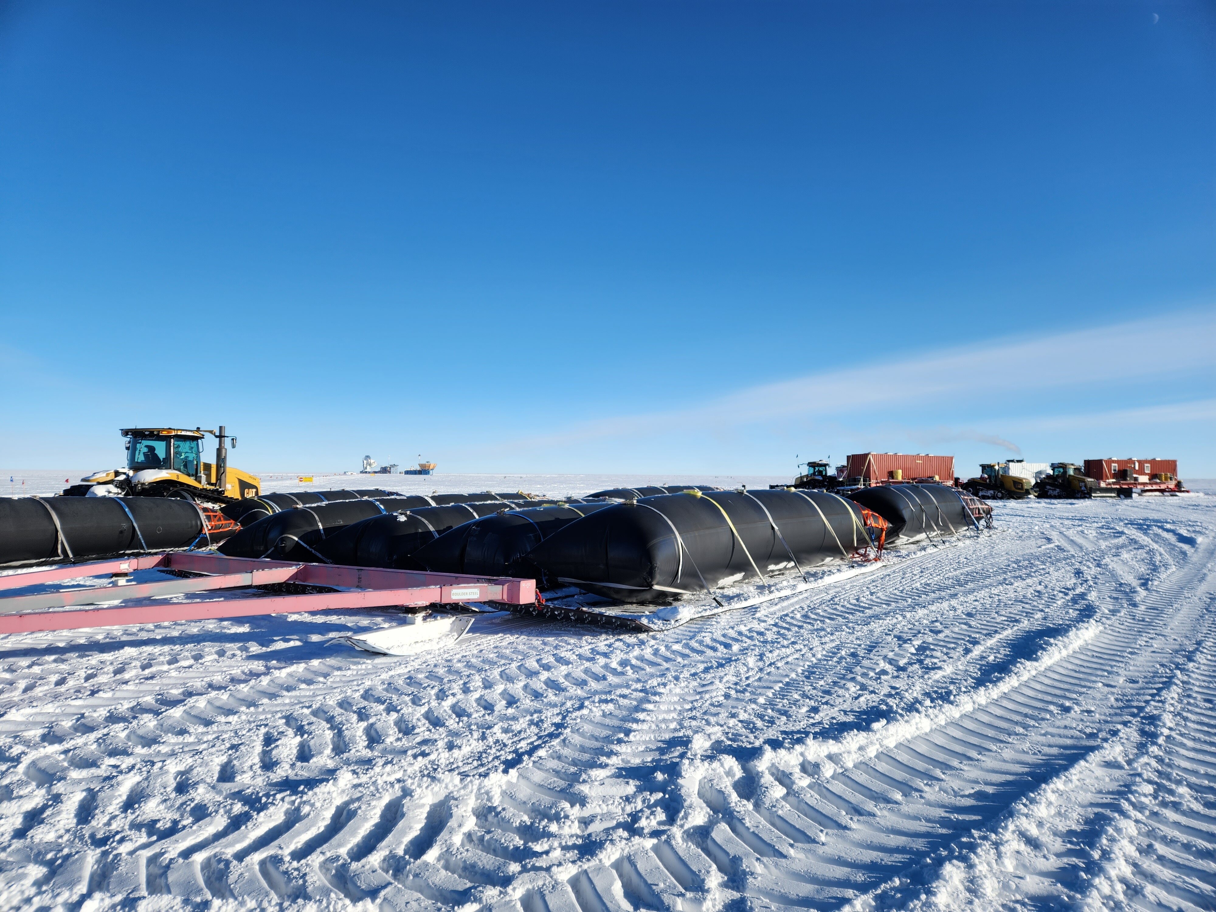
SPoT was started in 2008, specifically to solve the prohibitive fuel and logistical expense of flying so many LC-130s to Pole to transport bulk, heavy goods. One of the primary items that SPoT hauls to Pole is bulk fuel. Large, flexible fuel bladders are filled with AN-8 at McMurdo. These are attached to tractors. The tractors crawl from McMurdo to Pole, dragging the precious cargo behind them.
The fuel efficiency of SPoT is significantly better! According to the same analysis from ERDC (again, available here), SPoT burns just 0.56 pounds of fuel in transit to transport a pound of fuel from McMurdo to the South Pole. This is a ~58% reduction in fuel usage, compared with LC-130 flights.
Currently, as of 2023, we run 3 SPoTs per summer: SPoT 1, 2, and 3. Each trip takes several weeks to drive from McMurdo to Pole and back again.
The folks who work SPoT spend several weeks prepping in McMurdo. Then they depart McMurdo, drive across the Ross Ice Shelf, ascend thousands of feet up the Leverett Glacier, and then trudge across the polar plateau, though a vast field of Sastrugi, until they reach South Pole Station. The total one-way trip is about 1,030 miles.
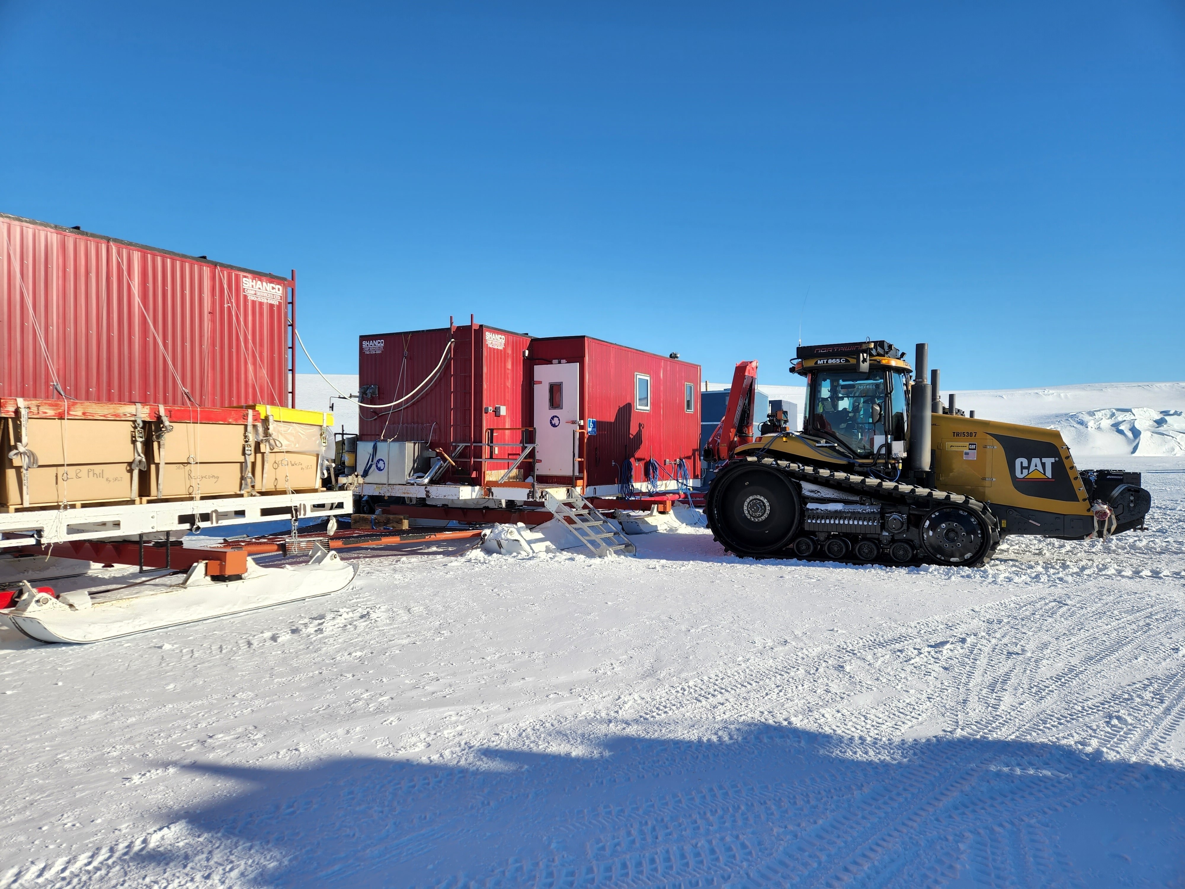
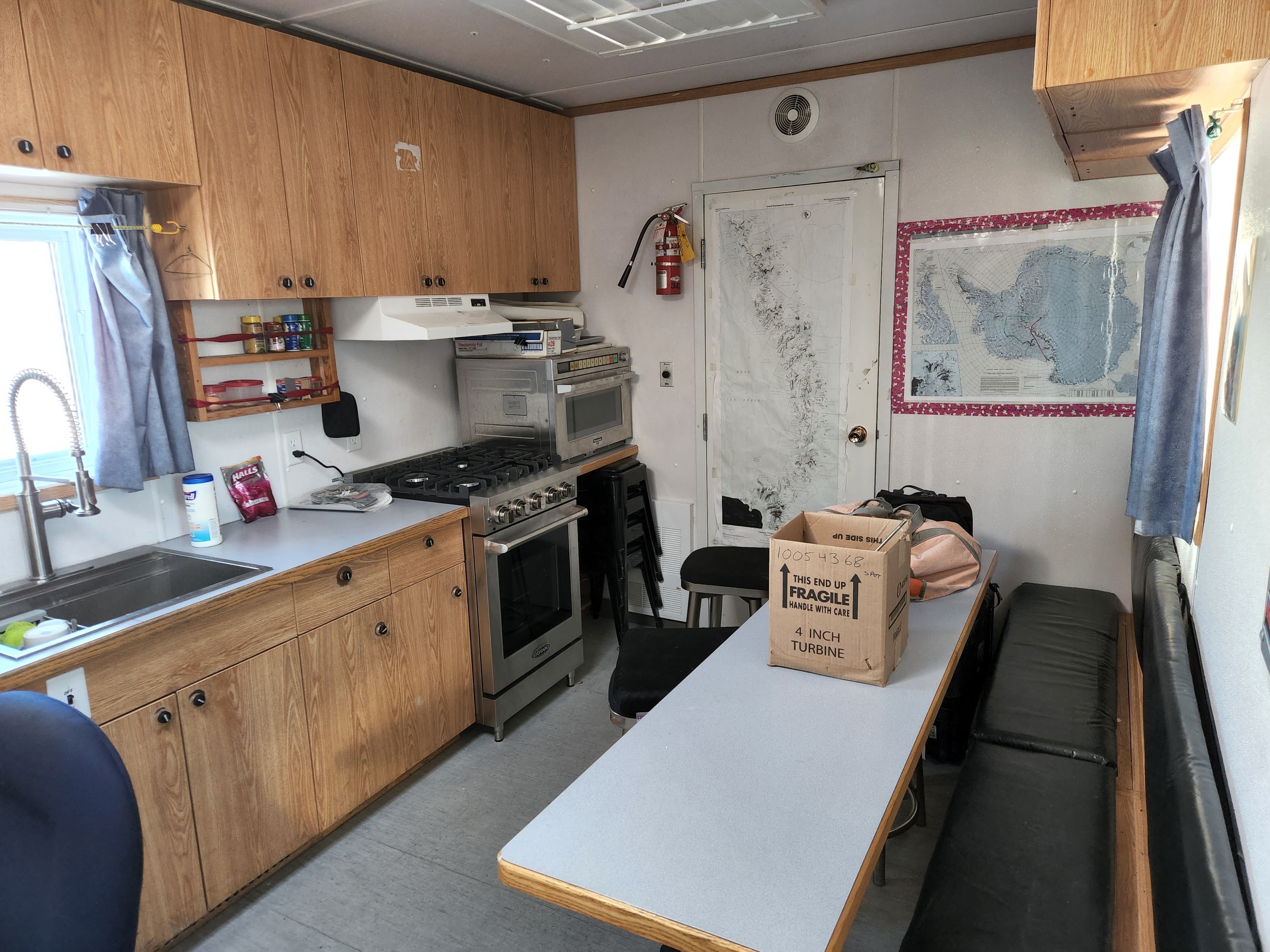
In addition to cargo destined for Pole, the SPoT team drags along everything they need for safety and (relative) comfort along the way. This includes their own electrical generators, a cooking / cleaning / berthing module, restroom facilities, and all the tools and spare parts they need to keep their tractors running along the way.
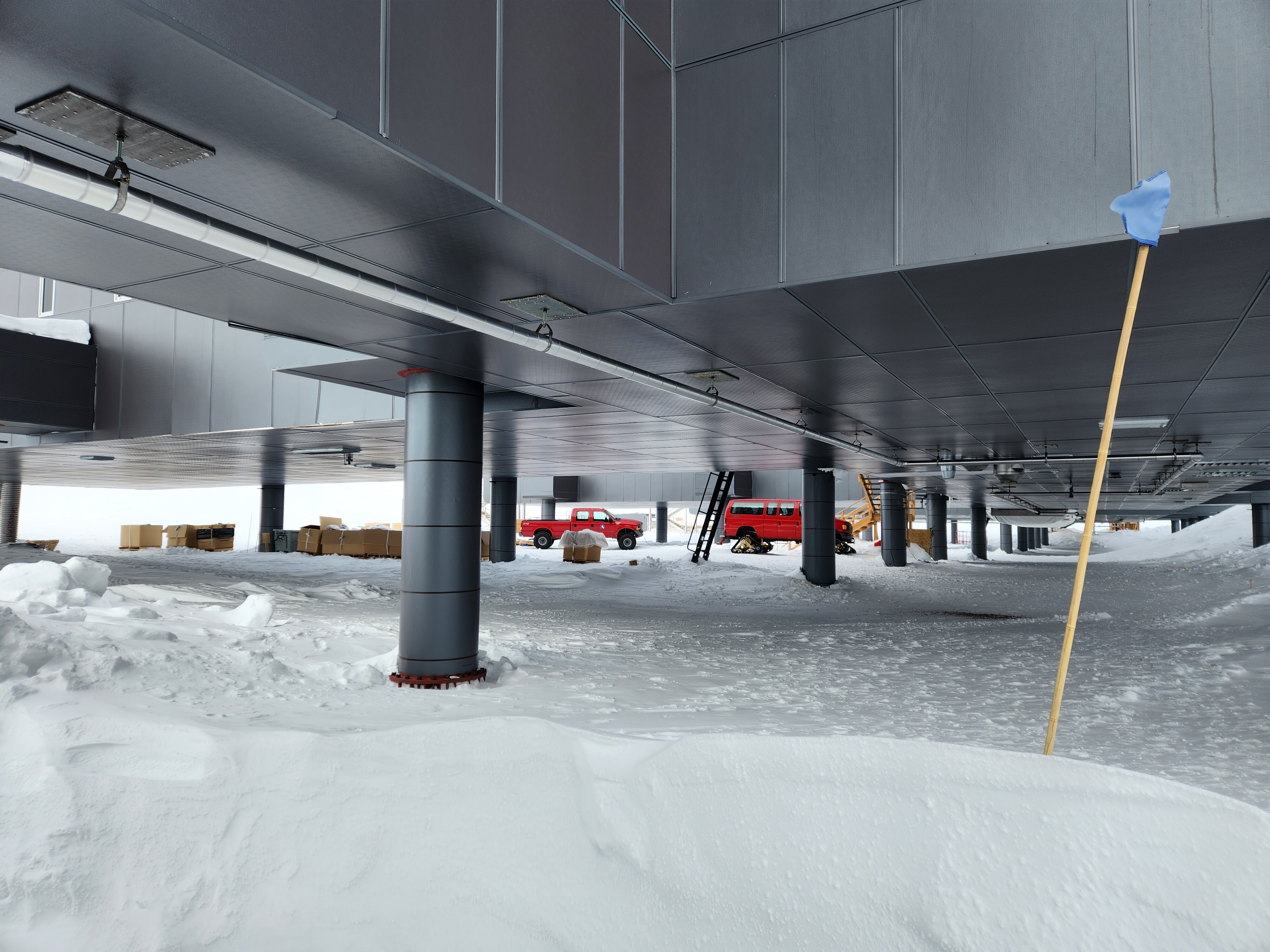
Once SPoT gets to Pole, they offload their bulk fuel into our storage tanks:
SPoT then returns to McMurdo, hauling whatever “retrograde” cargo we have ready for them. Trash, old parts, etc. The fuel bladders are inflated with air, so they behave on the journey back while being dragged across the polar plateau.
Significant engineering has gone into designing the tow-behind systems used on SPoT, to ensure that the fuel bladders don’t break, rupture, or dig into the snow. You can find some interesting technical details about the design of the SPoT tow-behind systems here (1.3 MB PDF), again from the US Army Corps of Engineers ERDC.
Fuel Storage at Pole
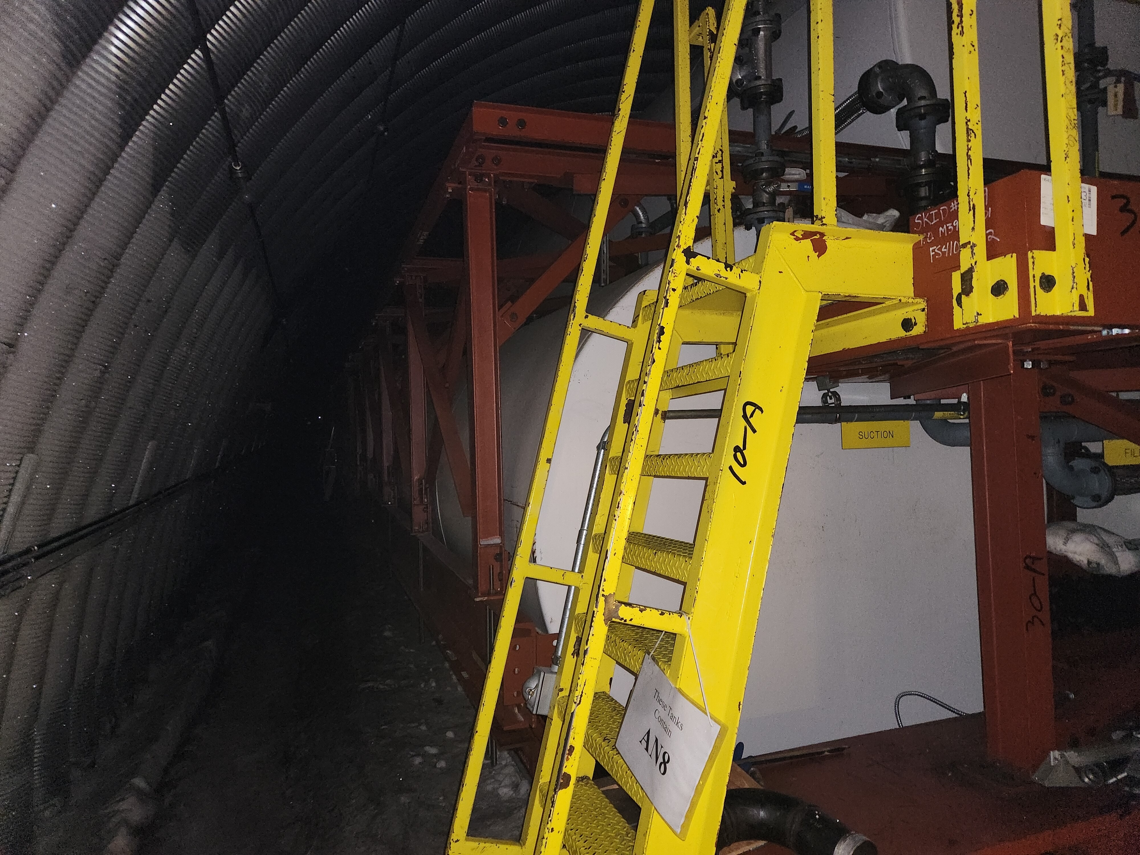
Bulk fuel here at Pole is stored in the fuel arch, yet another arch that has long since been buried.
We store hundreds of thousands of gallons of bulk fuel here – enough for the long dark winter, with a healthy reserve. Fuel management is a complex process. We have to take into consideration our own baseline electrical and heating demands, plus any fuel we need to provide to field camps or science projects that operate their own equipment, plus any fuel we need to provide to airplanes that pass through or are seasonally-based at Pole.
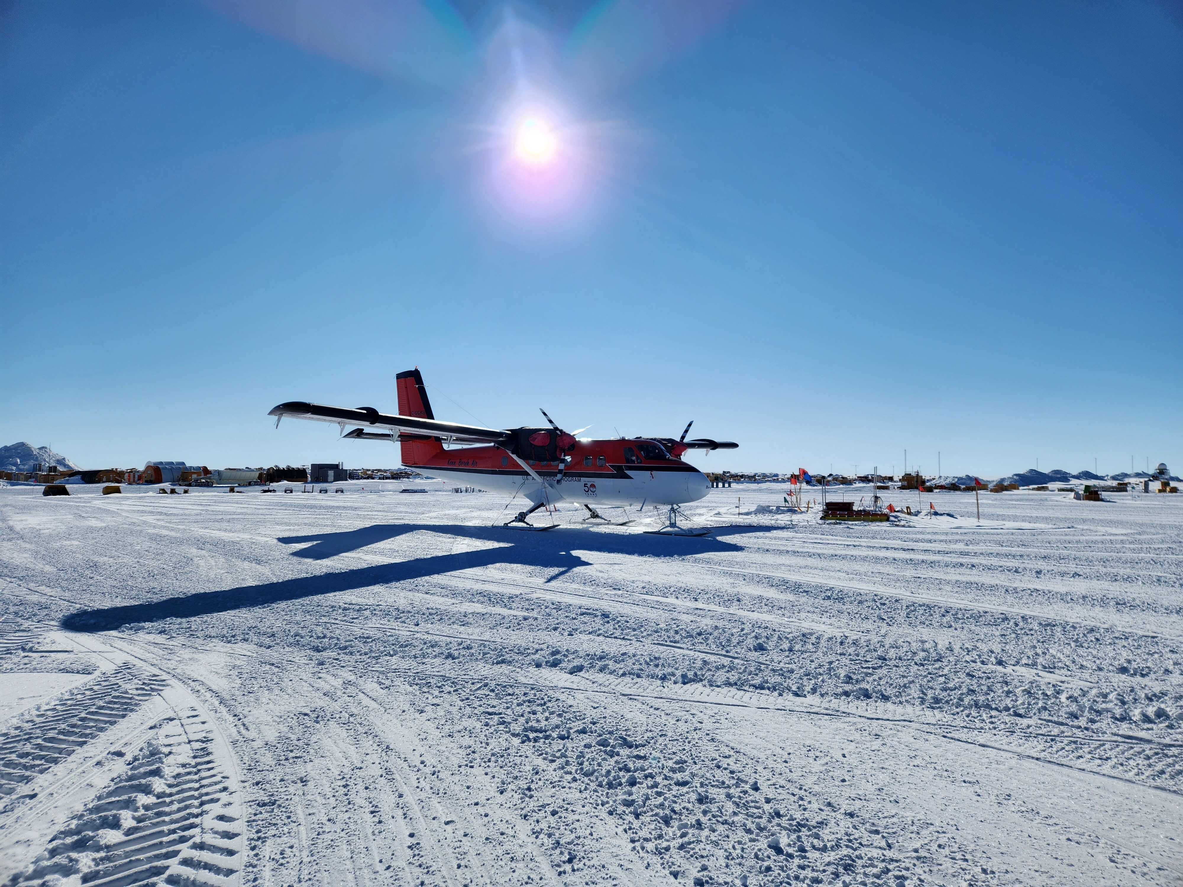
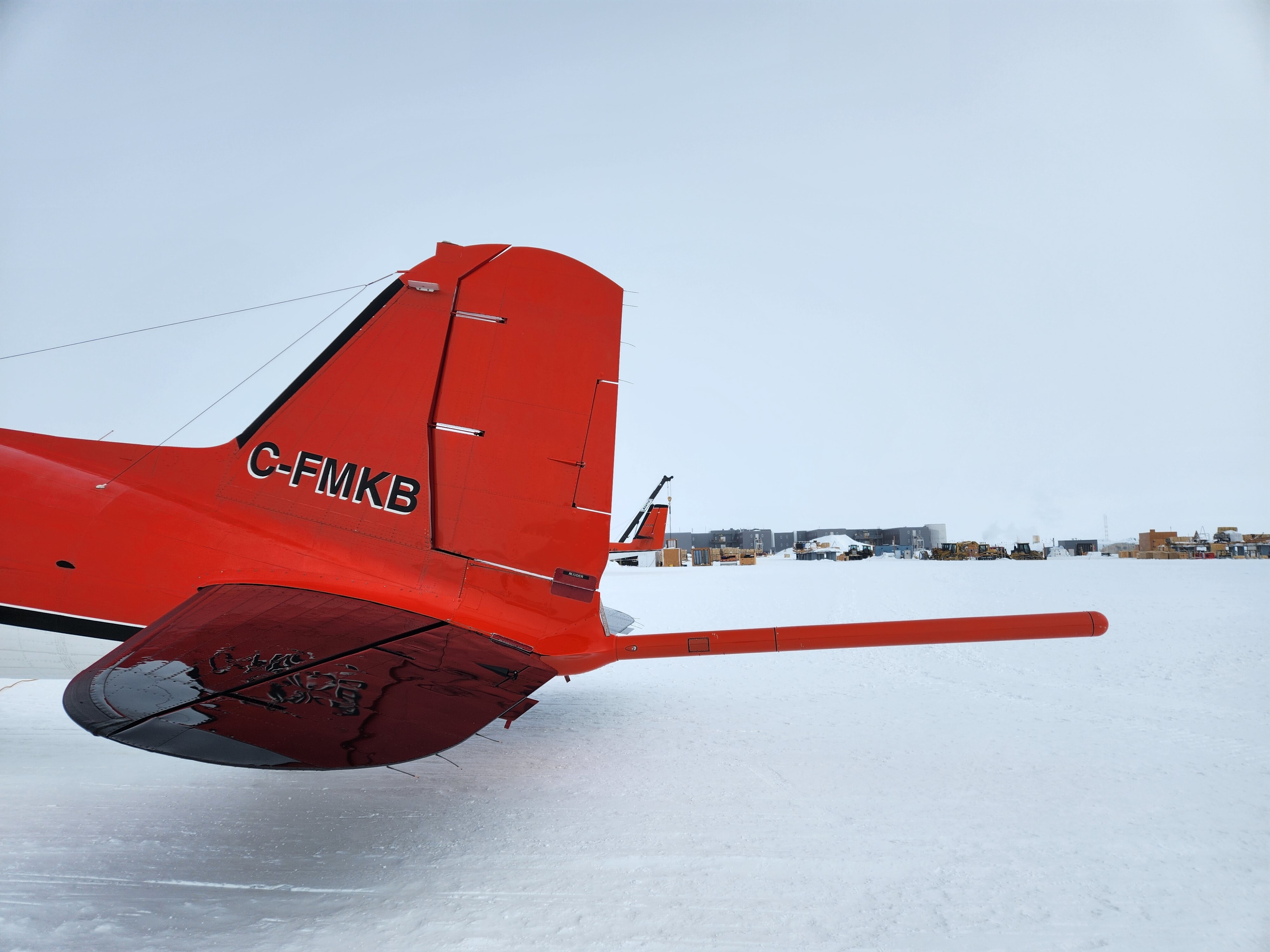
For example, Kenn Borek Air (based in Canada) operates Twin Otters and Baslers across Antarctica in support of the United States Antarctic Program. They typically deploy their planes from Canada to McMurdo by sending then down from Canada, through South America, to the Antarctic Peninsula with a stop at Rothera for fuel, across the Polar Plateau with a stop at the South Pole for fuel, and then onward to McMurdo.
In addition, planes themselves are sometimes stationed at South Pole, depending on what science is being performed. For example, KBA operated regular Basler flights based out of the South Pole during Summer 2022/2023, in support of the COLDEX project. These flights required us to budget and allocate fuel.
For contingency and resiliency, we also store several caches of emergency fuel in tanks around campus. In the event of a catastrophic loss of utility of our fuel arch, we could haul some of our surface tanks over to station, hook them up, and maintain safe operations.
Power Generation - Primary
Our primary power generation occurs in the station’s main power plant, located in the first of three arches. I wrote more about the overall structure of the arches in my post about the Beer Can.
Power Plant Overview
Upon entering the power plant, you are required to sign in and tag in. This is an industrial facility, and it’s important to know who is in here at all times.
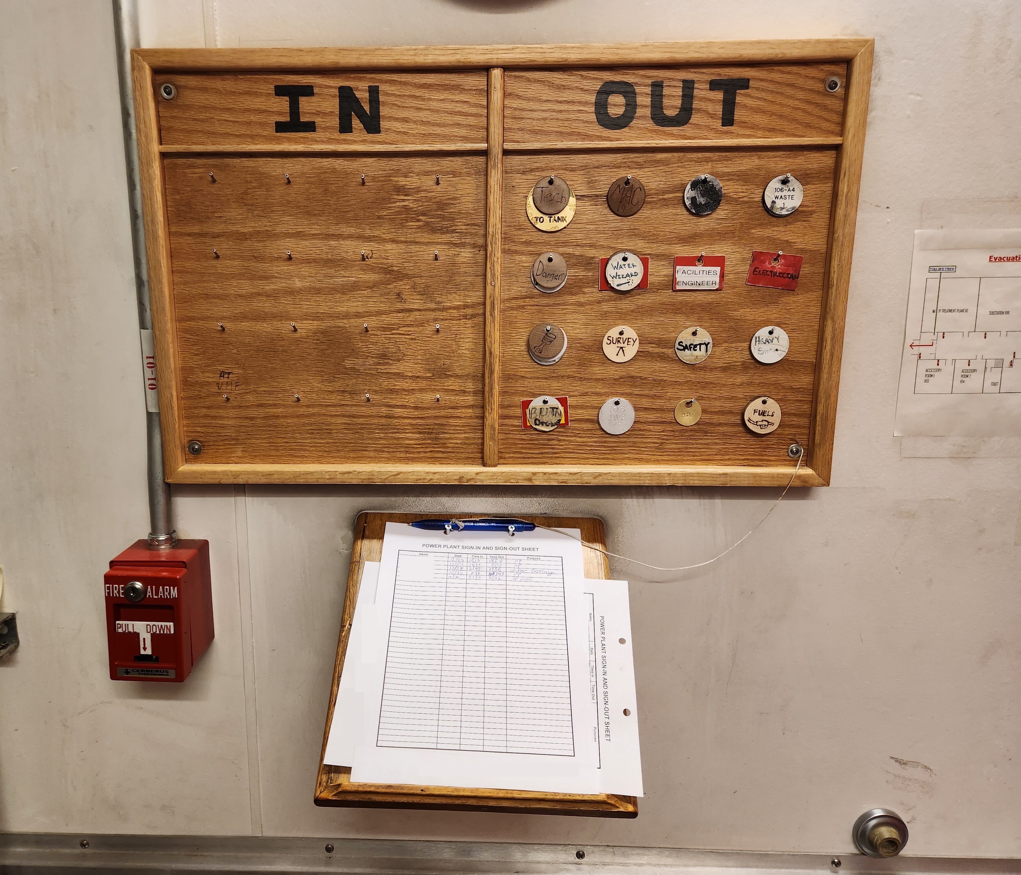
In the event of an incident, there are specific, nonstandard hazards in this facility, including the risk of CO2 release from our fire suppression system. Knowing who (if anyone) is still in the facility is an important part of our decision-making process when responding to an incident.
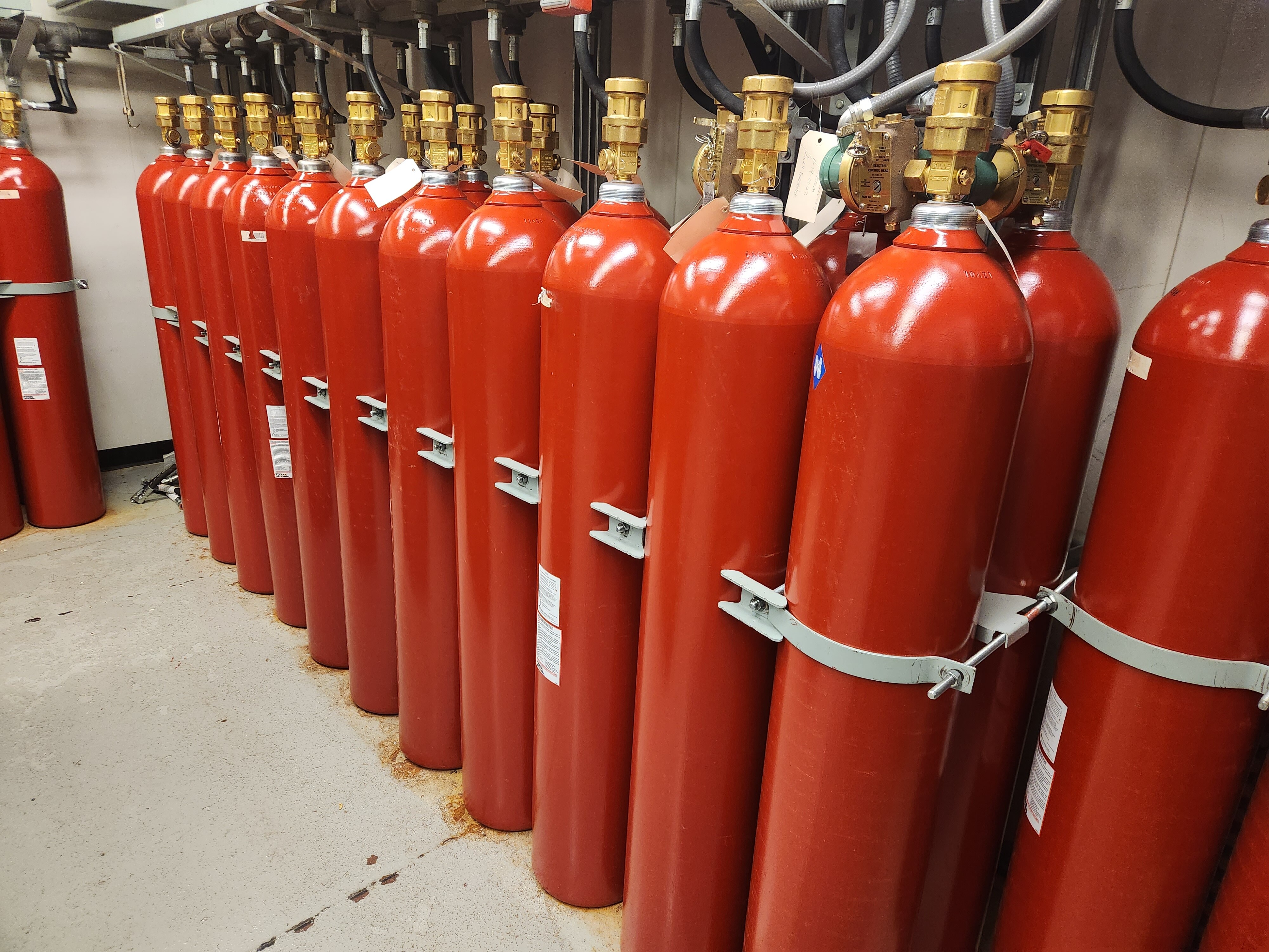
A CO2 system is effective at extinguishing a variety of types of fire, but in the event the system were deployed, it has the potential to create an environment that is Immediately Dangerous to Life or Health (IDLH).
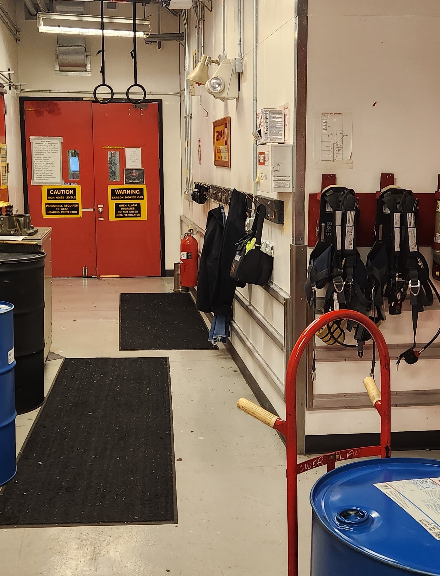
Deep in the power plant, you’d be forgiven if you forgot you were physically at the South Pole! The plant interior is similar in style to any other industrial setting you’d find back home. There are no windows, and the plant is heated.
Here’s the plant entrance hallway:
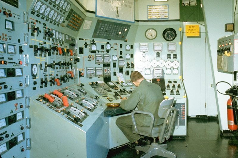
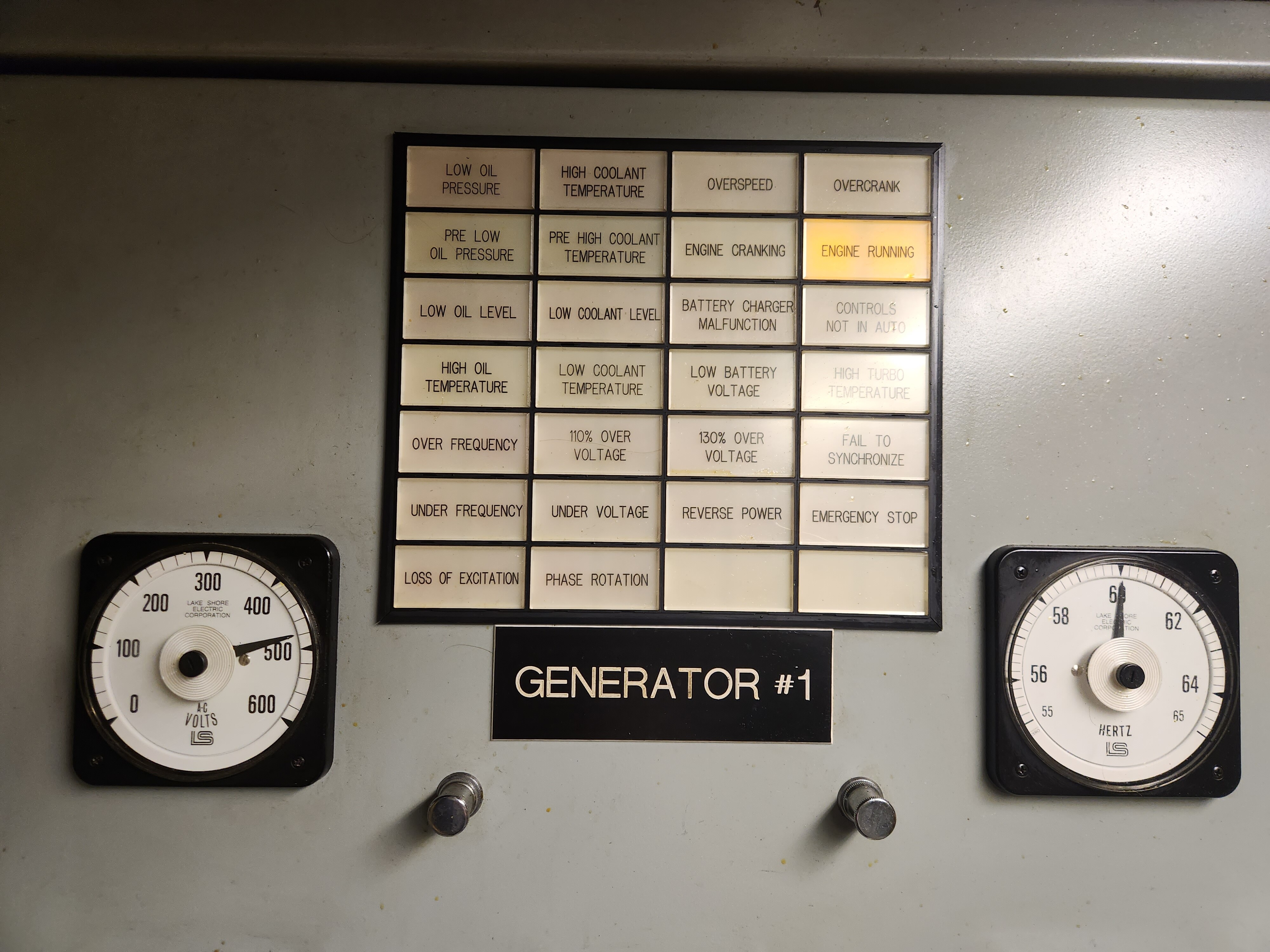
Here’s the plant control room:
Fun fact – the power plant is home to the World’s Southernmost Flush Toilet! The Power Plant Arch is physically closest to the geographic South Pole, which “moves”, relative to the station, about 33 feet every year. Given the direction of movement, this will remain the World’s Southernmost Flush Toilet for the foreseeable future, barring any major construction in the path of travel.
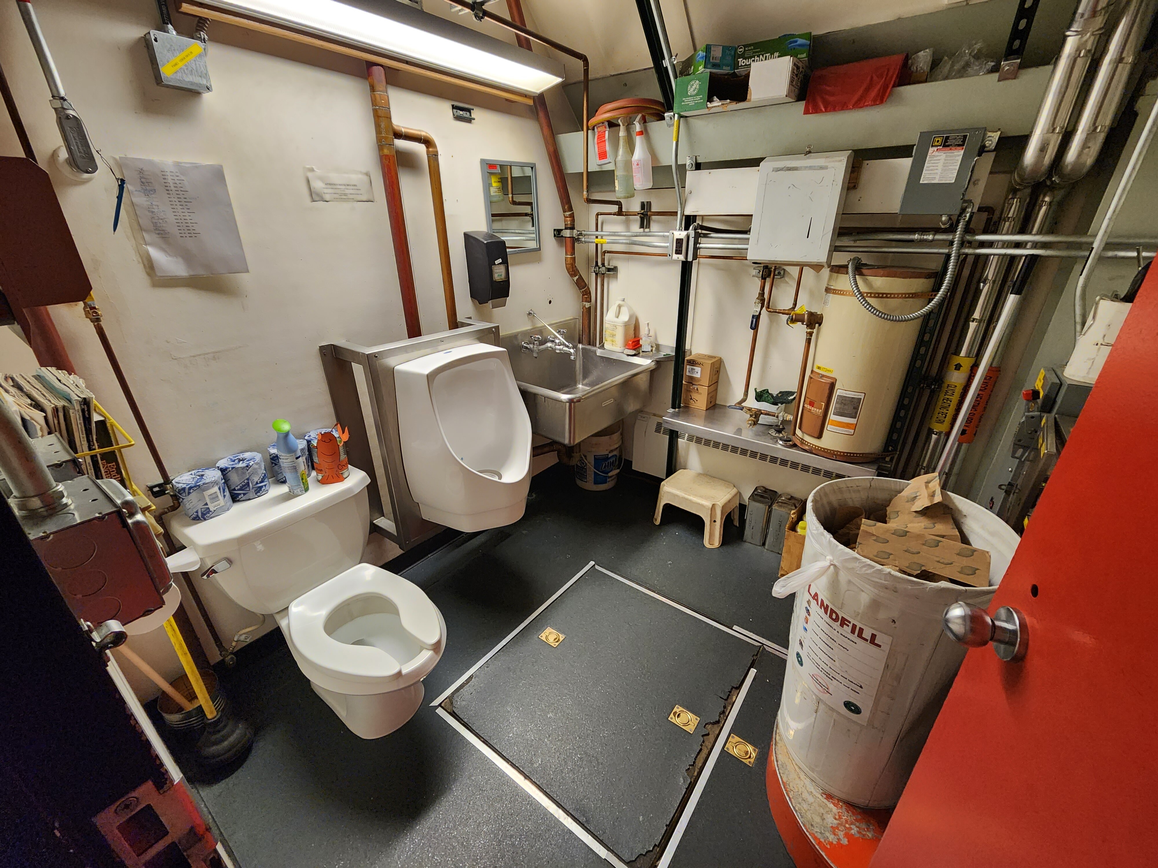
(Geographically-astute readers will note that the geographic pole itself isn’t moving – it’s at a fixed, absolute location on Earth. It’s actually the ice sheet, and therefore all our buildings, that are moving! When I say “the pole is moving”, it’s because we physically move the geographic pole marker every year to compensate for the movement of the ice sheet.)
The power plant is the only place in the arches with a bathroom. This makes it a popular spot for workers in the other arches, who are able to walk to the power plant to use the bathroom. This is a welcome amenity, because the alternative is having to climb all 90 beer can stairs to the elevated station.
Power Plant Fuel Management
Our tour begins with a look at how fuel gets here.
Per the section above, we store hundreds of thousands of gallons of fuel in our fuel arch. Fuel is pumped into the power plant via piping from the fuel arch, and it is stored in two large day tanks. This ensures some on-premise resiliency. In the event of a disruption or maintenance in the fuel distribution network, we can continue operations.
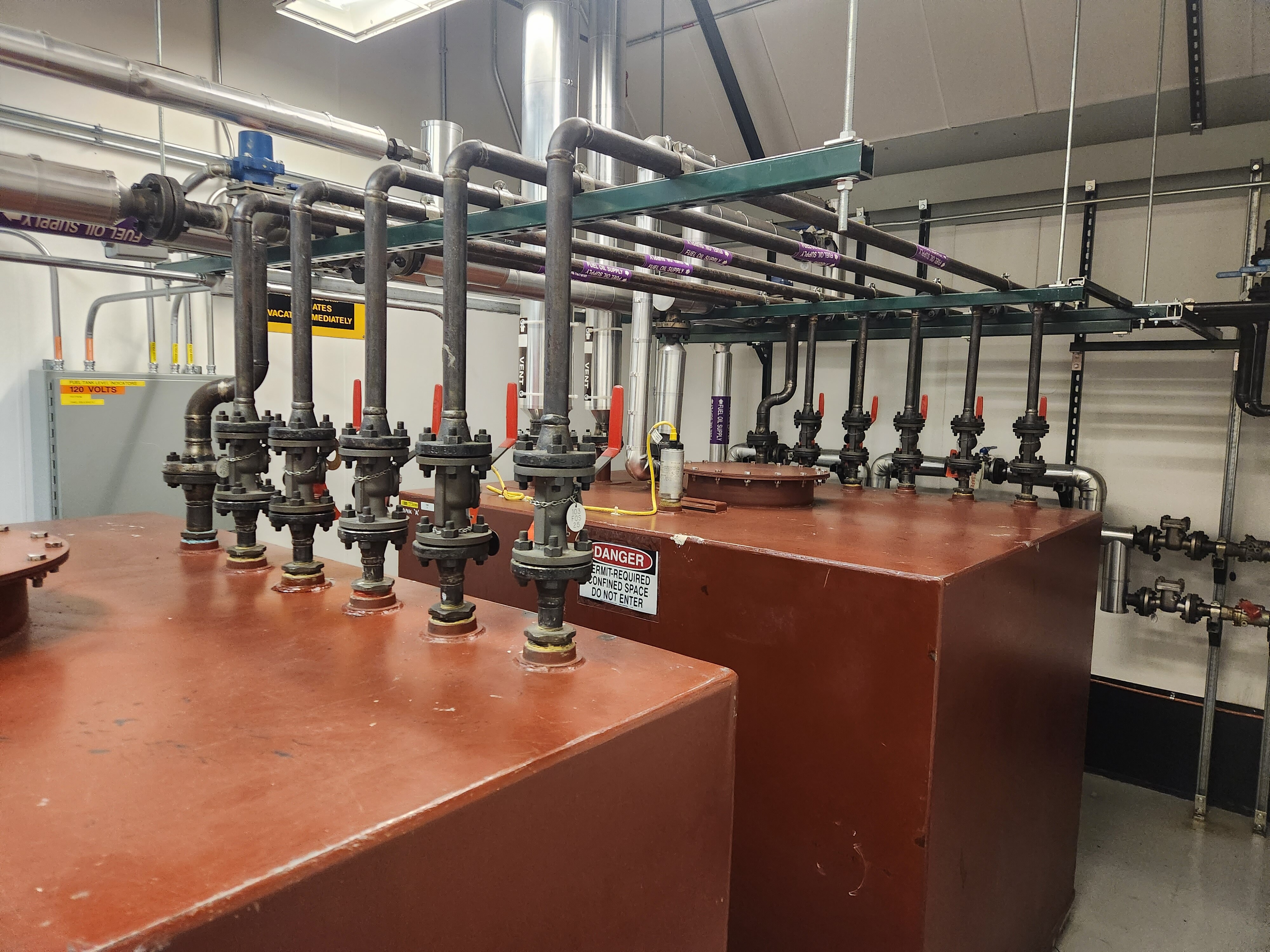
Fuel travels from the day tanks into the power plant engine room via a series of pipes:
Power Plant Generators
Moving on, we enter the main engine room, which occupies the majority of the power plant arch.
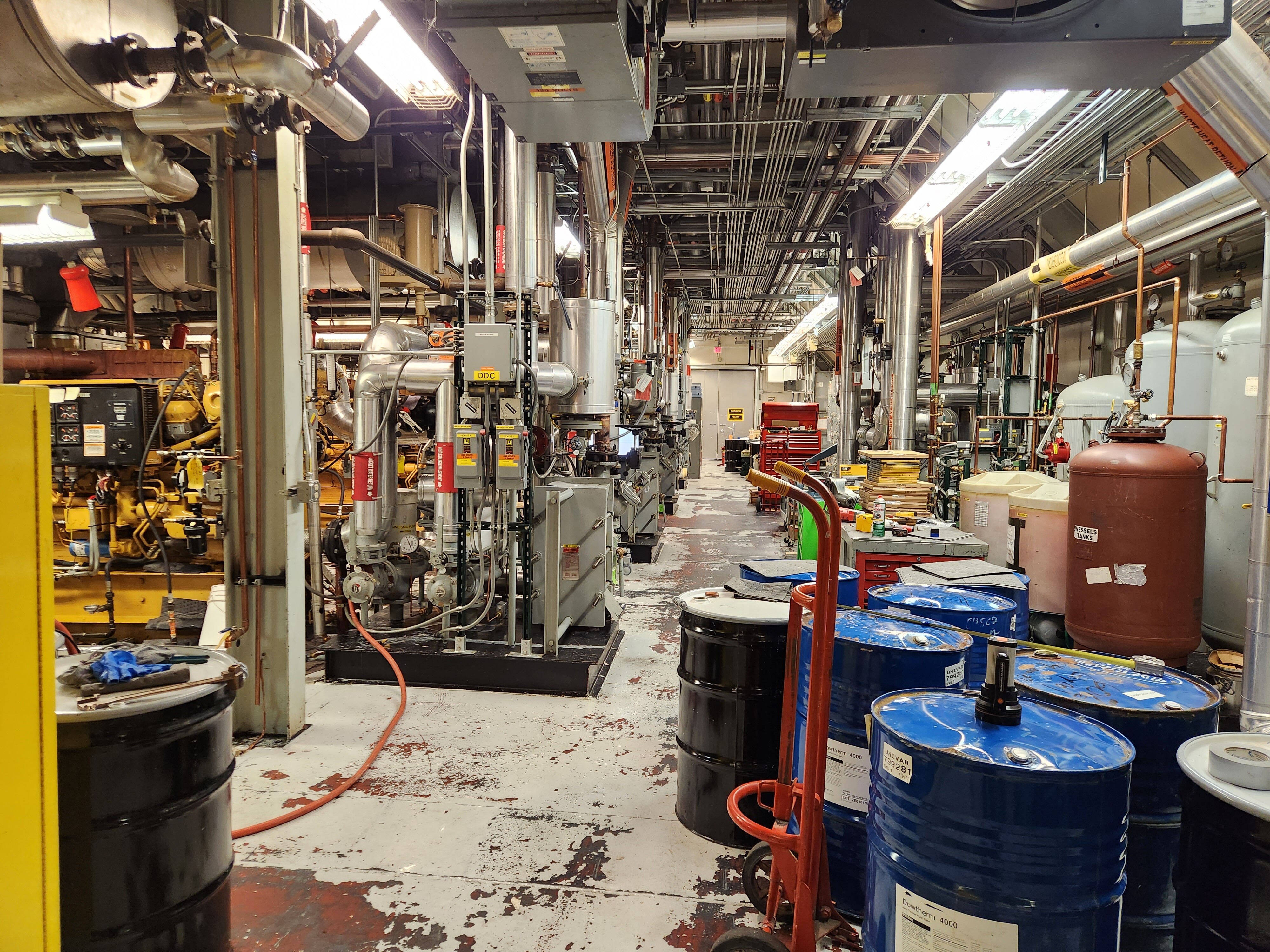
At the heart of the power plant are three CAT 3512B engines:
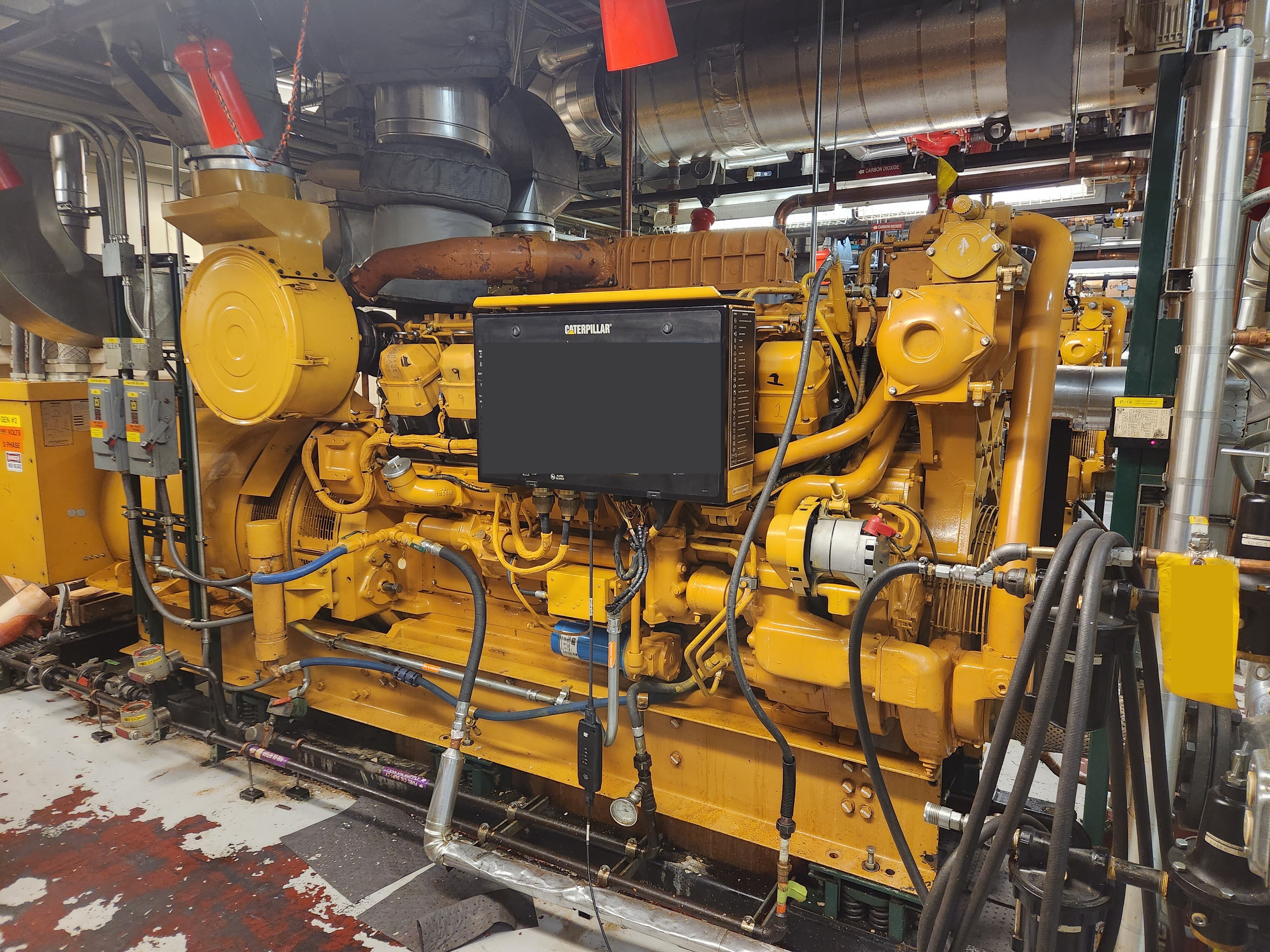
Each engine is coupled to a generator module, which is used to generate power. Each of these primary generators is rated for 750 kilowatts, after some de-rating due to the altitude and fuel blend. Remember, we’re at 9,301 feet nominal elevation, but the air pressure is equivalent to an even higher elevation, often upwards of 11,000 feet. See my post on pressure altitude for more information.
We run one generator at a time. One is in standby, ready to start and pick up load if the primary generator trips offline or fails. One is offline, which allows for maintenance. We swap generators periodically, in order to keep them evenly worn and ensure we can perform regular maintenance as needed.

The plant was also built with a fourth, “peaking” generator, rated at 250 kilowatts, which was designed to come online and pick up any peak loads that couldn’t be comfortably met by the primary generator.
While this was an important consideration when the plant was built, today, the peaking generator is not used. Power demand fits comfortably within the capacity of a single, primary generator.
We’re careful to ensure that new science projects fit within our power budget. This is a point of concern among large science projects here – see this article in “News from Science”, a publication by the American Association for the Advancement of Science (AAAS).
We also have the ability, through electronic controls, to set usage schedules for flexible loads. This allows us to manipulate the demand curve as needed. In practice, this is rarely needed, but it’s an option. Power demand, including peaks and troughs, is generally stable enough to keep our online generator operating within its rated load factor.
In order to swap generators, the process is as follows:
- Complete some pre-checks.
- Start and warm up a second engine. Complete some additional checks with the second engine running at no load.
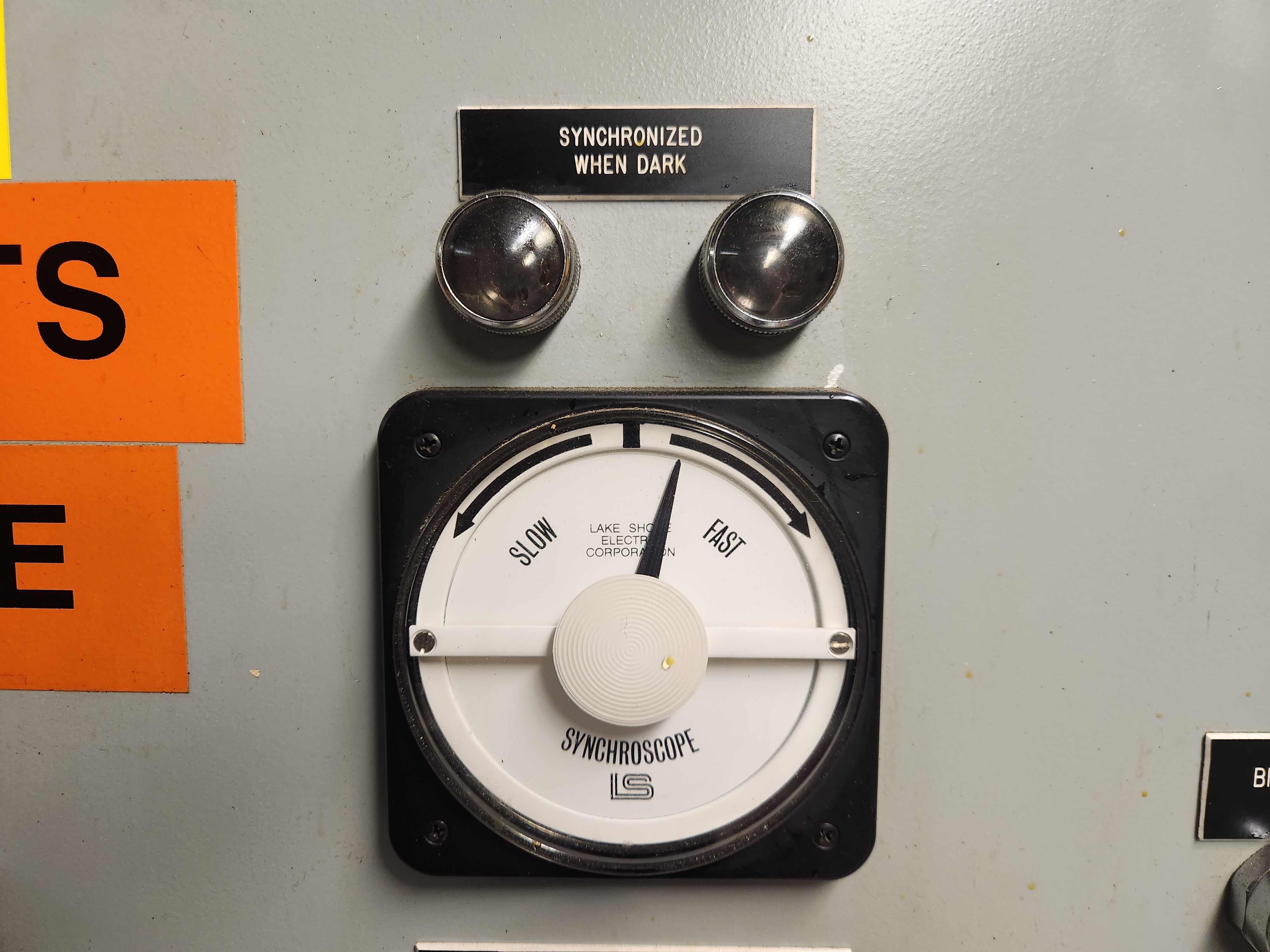
- Synchronize the second generator’s electrical output with the existing online generator, and then close the breaker, which brings the second generator online. This is normally done automatically.
- Run with both generators online for a few minutes, with grid load shared between them. A load sharing module handles this automatically. Both generators are magnetically-coupled at this point and will maintain the exact same speed.
- Complete some additional checks on the second generator, now that it’s carrying a load.
- Open the breaker to take the first generator out of the system, let it complete an idle / cooldown cycle, then shut it down.
All of this is done semi-automatically by our control software, but we do have the ability to manually synchronize generators and manually transfer loads if needed.
Power Generation - Emergency
For resiliency, we have three primary generators in our main power plant. This means we can have one running, one in standby, and one offline for maintenance.
In the event of a catastrophic loss of utility of our power plant, we have an entire, separate, emergency power plant, located inside the elevated station itself. This is known as the “EPP”, or Emergency Power Plant.
The EPP is located in the “Lifeboat”, which is our emergency wing of the station. The goal of the lifeboat is to ensure that there is a separate, protected space that we could use in case of a catastrophic loss of use of the rest of the station. It’s protected behind fireproof, insulated doors. In addition to redundant power, the lifeboat contains redundant heating, water, wastewater, communications, cooking, and berthing space. It certainly wouldn’t be comfortable, but the entire winterover crew could survive in the Lifeboat if necessary.
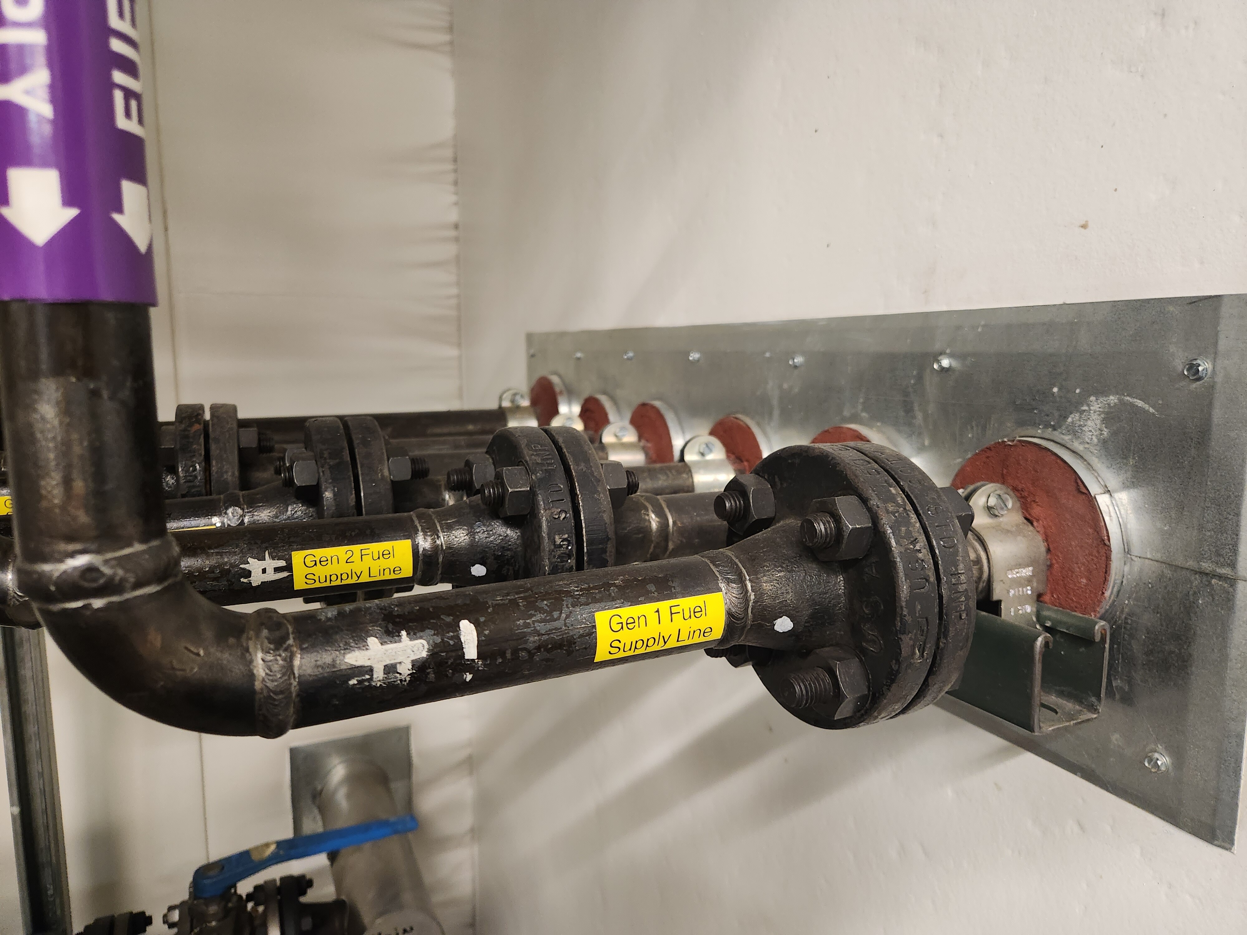
The EPP has its own AN-8 day tanks, and we also have a direct external connection that we can use to fuel them from portable tanks. This provides resiliency, in the event that our primary fuel distribution network is disrupted.
During normal operations, the Lifeboat is just a normal wing of the station, hooked into standard station infrastructure. But in the event of an emergency, we could isolate all the systems mentioned above.
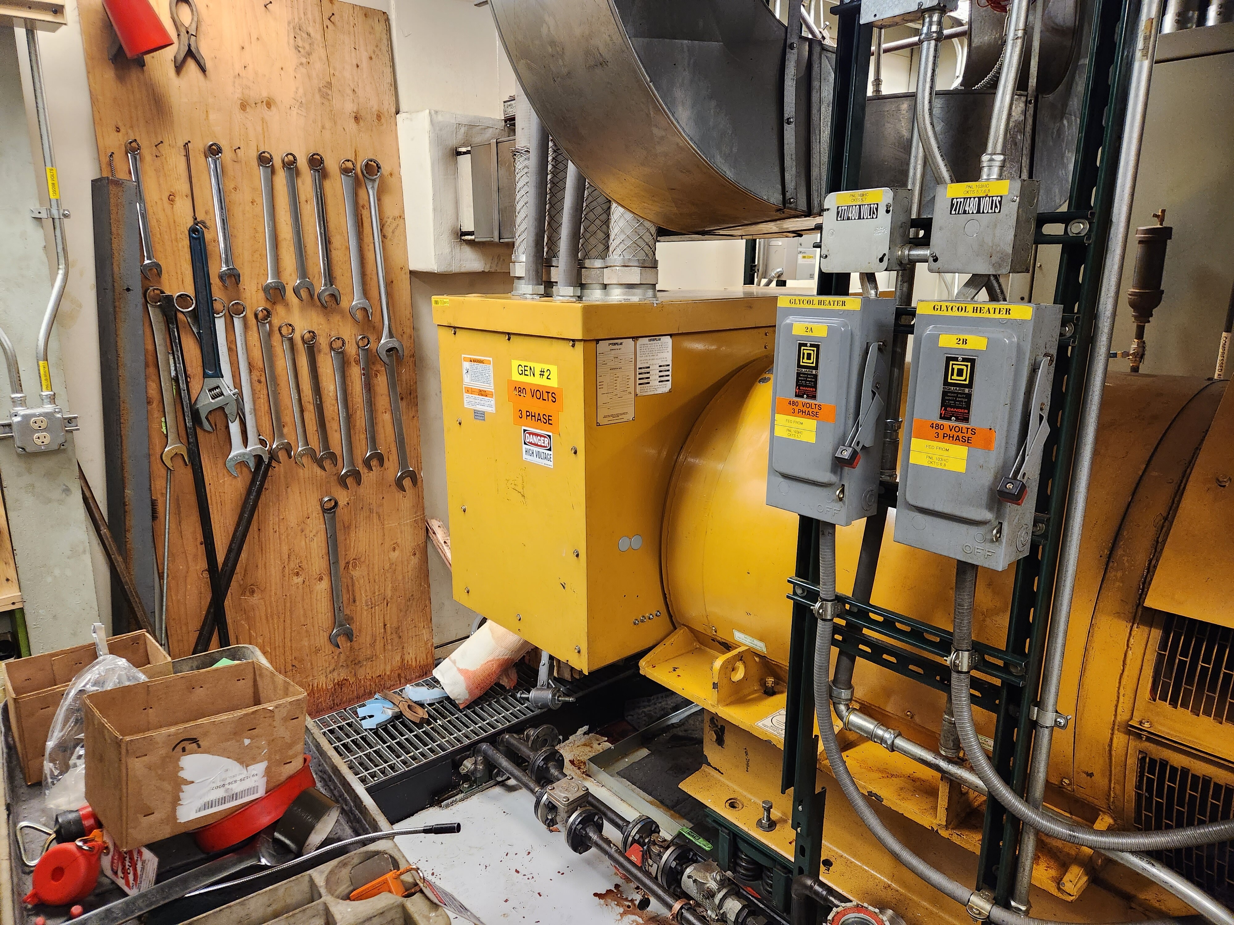
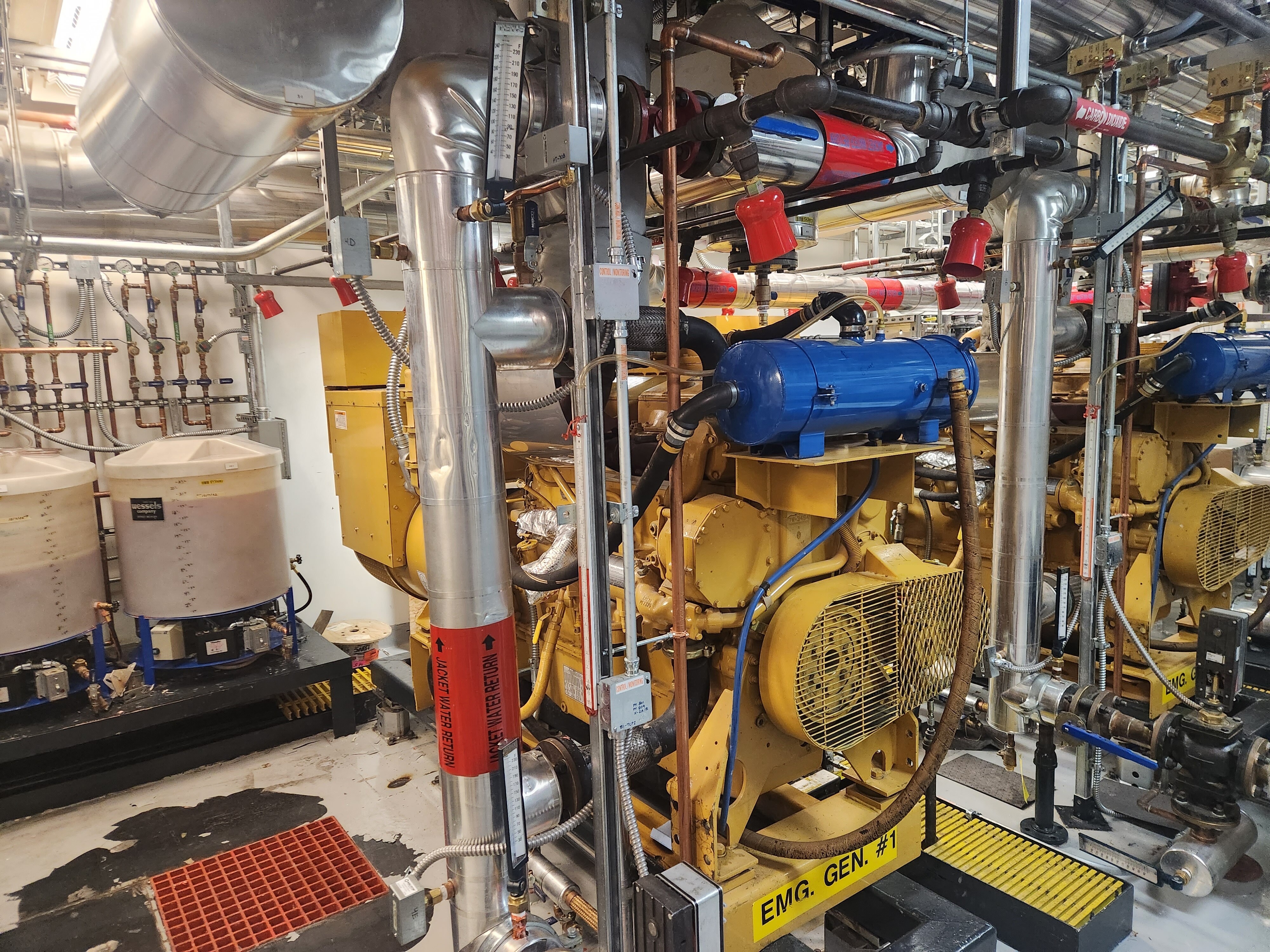
The Emergency Power Plant consists of two generators powered by CAT 3406B engines, with a capacity (after de-rating) of 250 kilowatts each. The emergency power plant also contains direct feeds to many of our major electrical load centers on campus, via separately-routed cabling that bypasses the main power plant entirely. This means that, in the event of a catastrophic loss of the distribution gear in the main power plant, we can still route power to various parts of the campus directly from the EPP.
We can use engine waste heat from the EPP generators to heat the Lifeboat. This is in addition to the direct AN-8 boilers we have here as well.
Most importantly, we have the ability to black start the EPP. This refers to the ability to start the EPP without relying on an existing external power source. This means we have sufficient battery capacity for critical engine and power management systems, fuel delivery that can temporarily function without externally-powered pumps, and manual electrical switchgear that we can use to energize portions of the station. In the event of a loss of power from the main power plant, we can bring the EPP online rapidly.
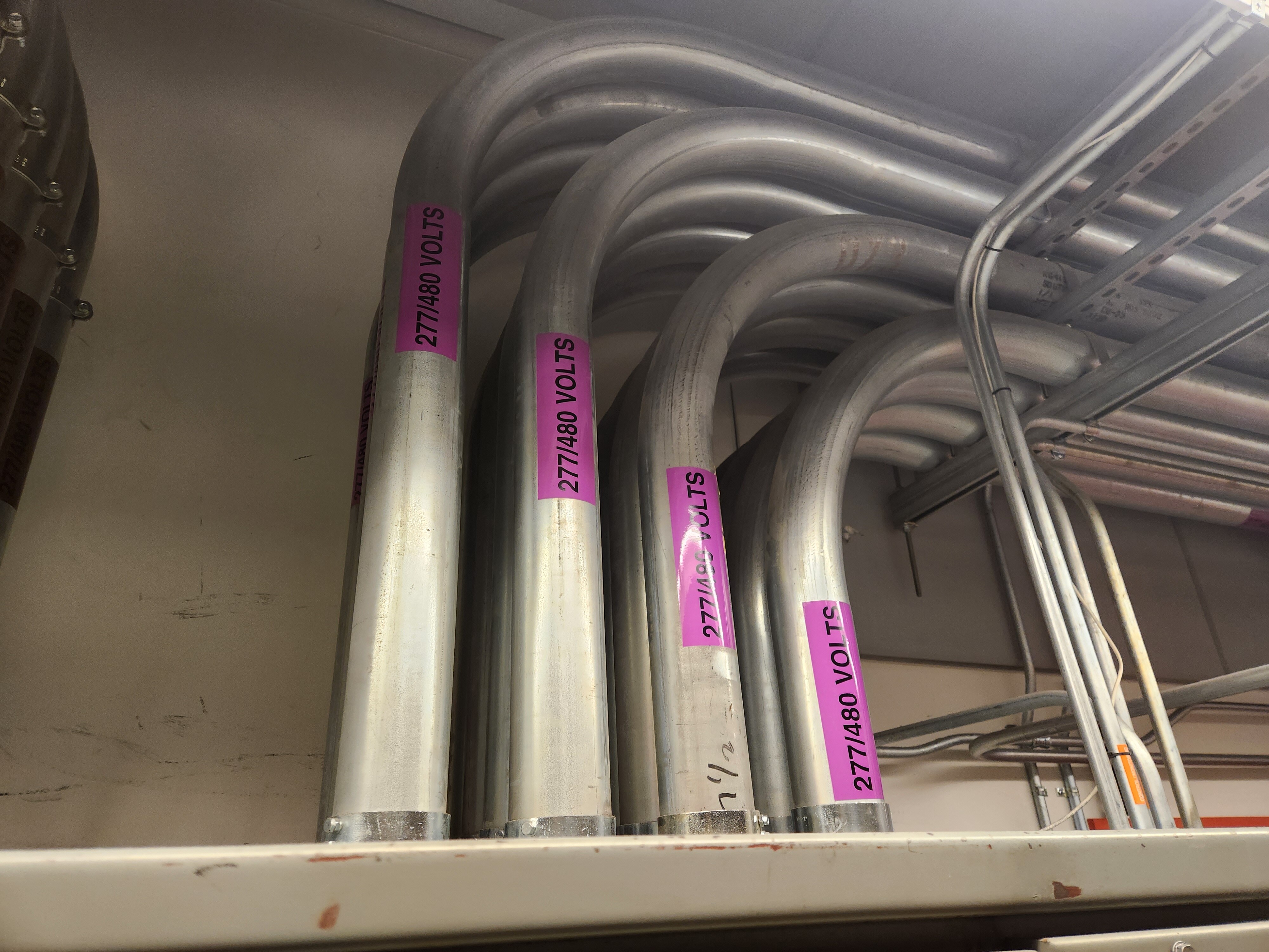
Electrical Distribution
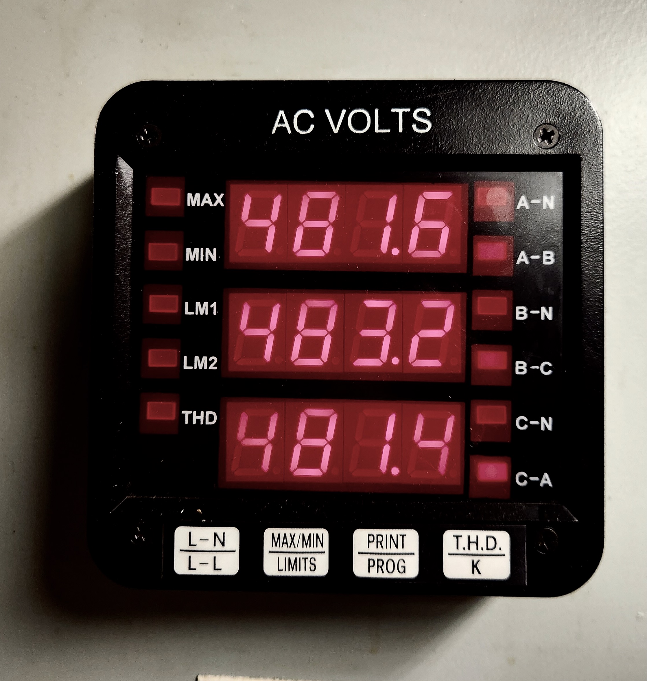
Both our power plants, the main power plant and the emergency power plant, generate 3-phase, 480/277 volt, 60 hertz power. This is a typical US standard for a plant of this size.
480 volts is also our standard distribution voltage for the majority of feeders around campus, with a few exceptions.
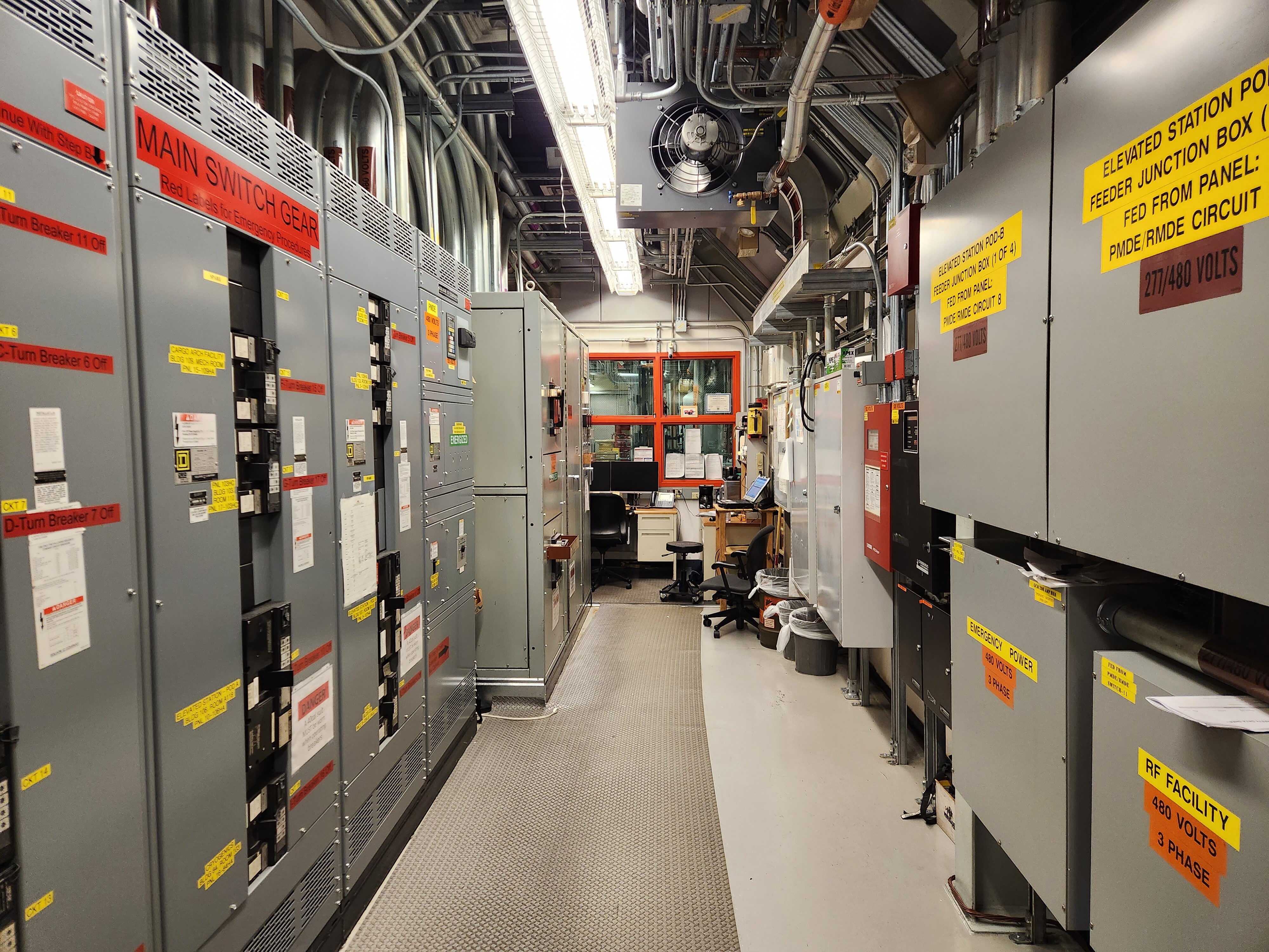
Main Distribution
Power from the running generator(s) is routed to a main generator bus, located in a cabinet inside the control room:
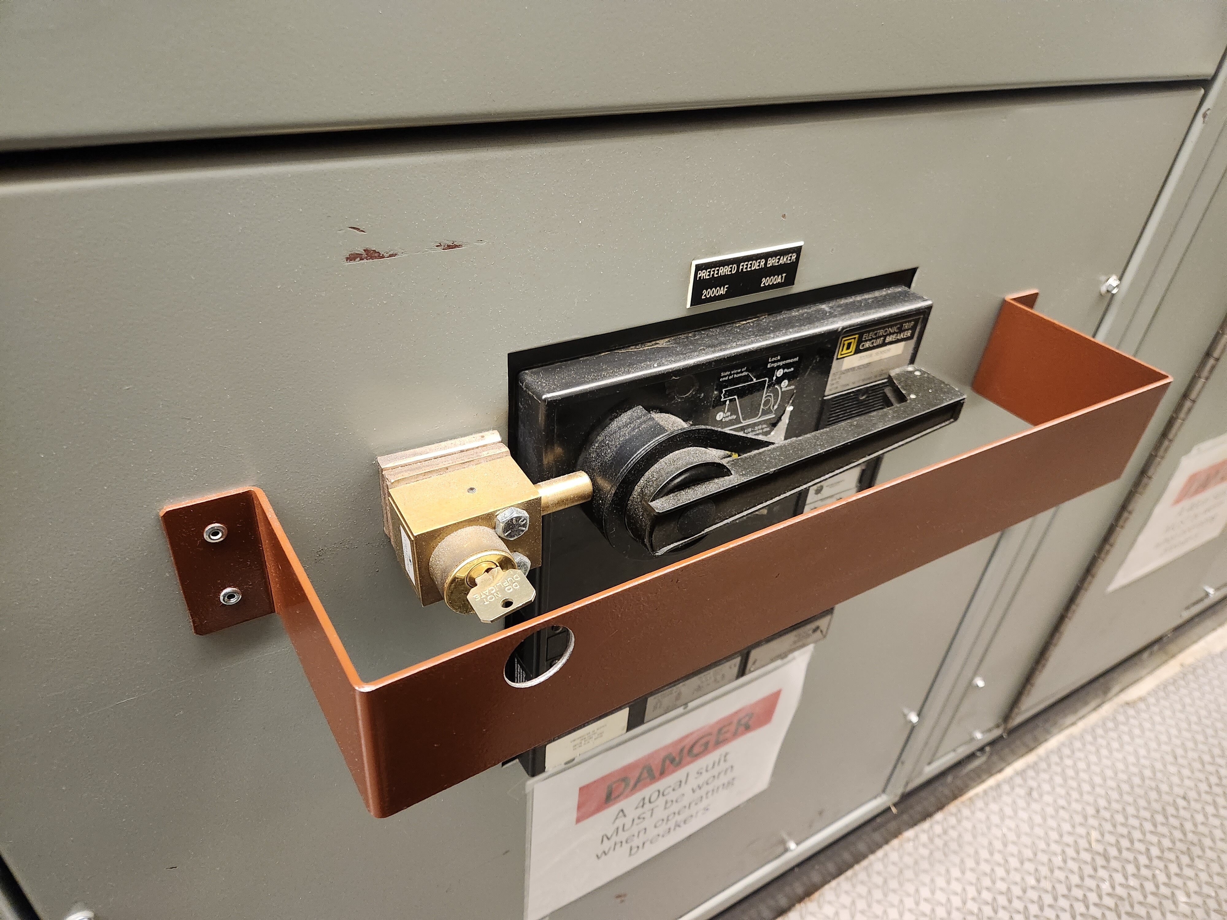
From there, we have a main breaker:
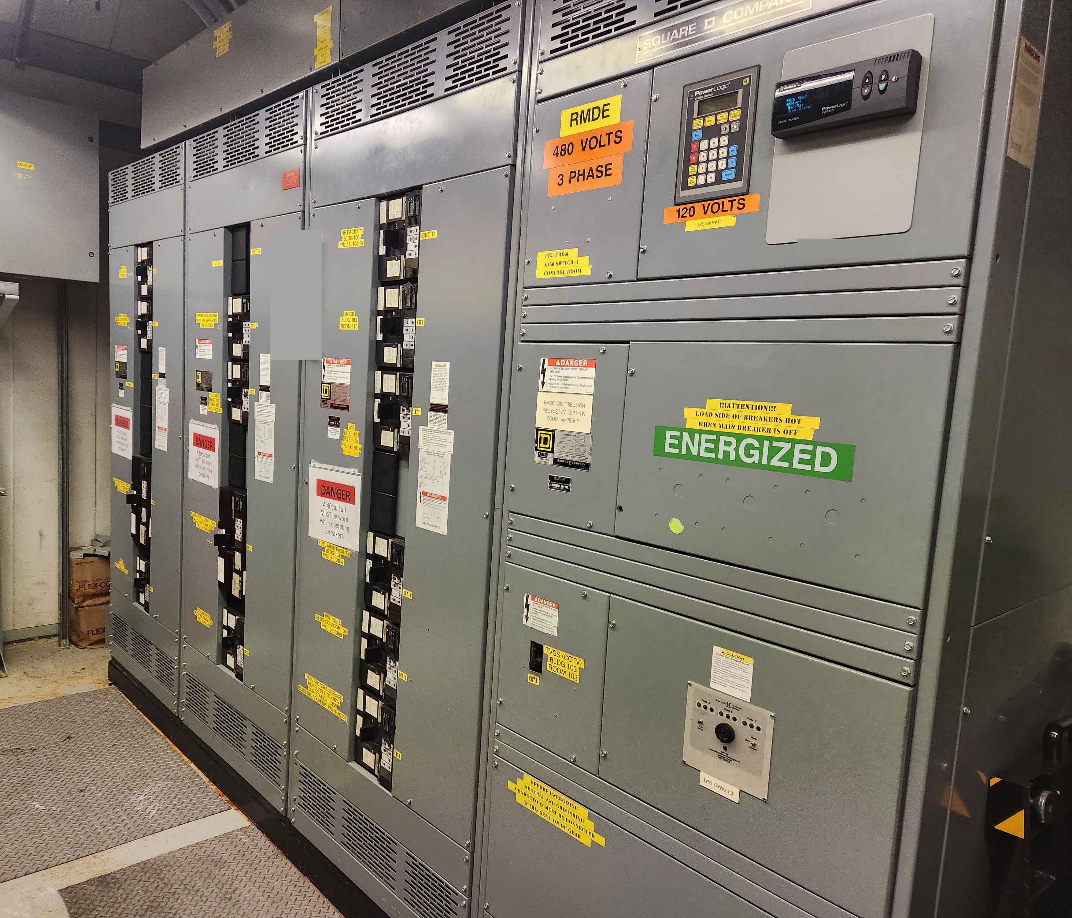
And then our main distribution panel. We have just over a dozen major feeders on campus:
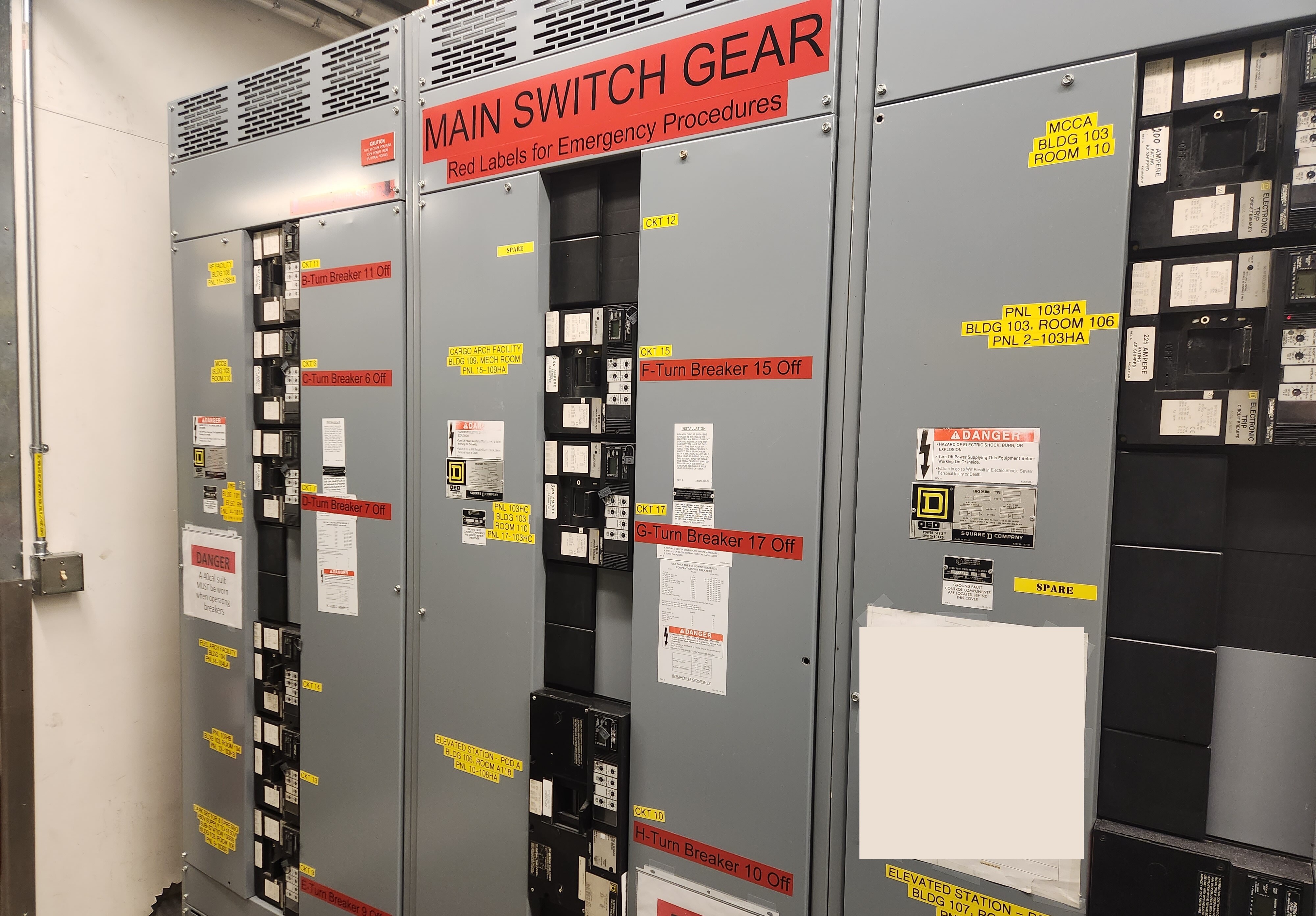
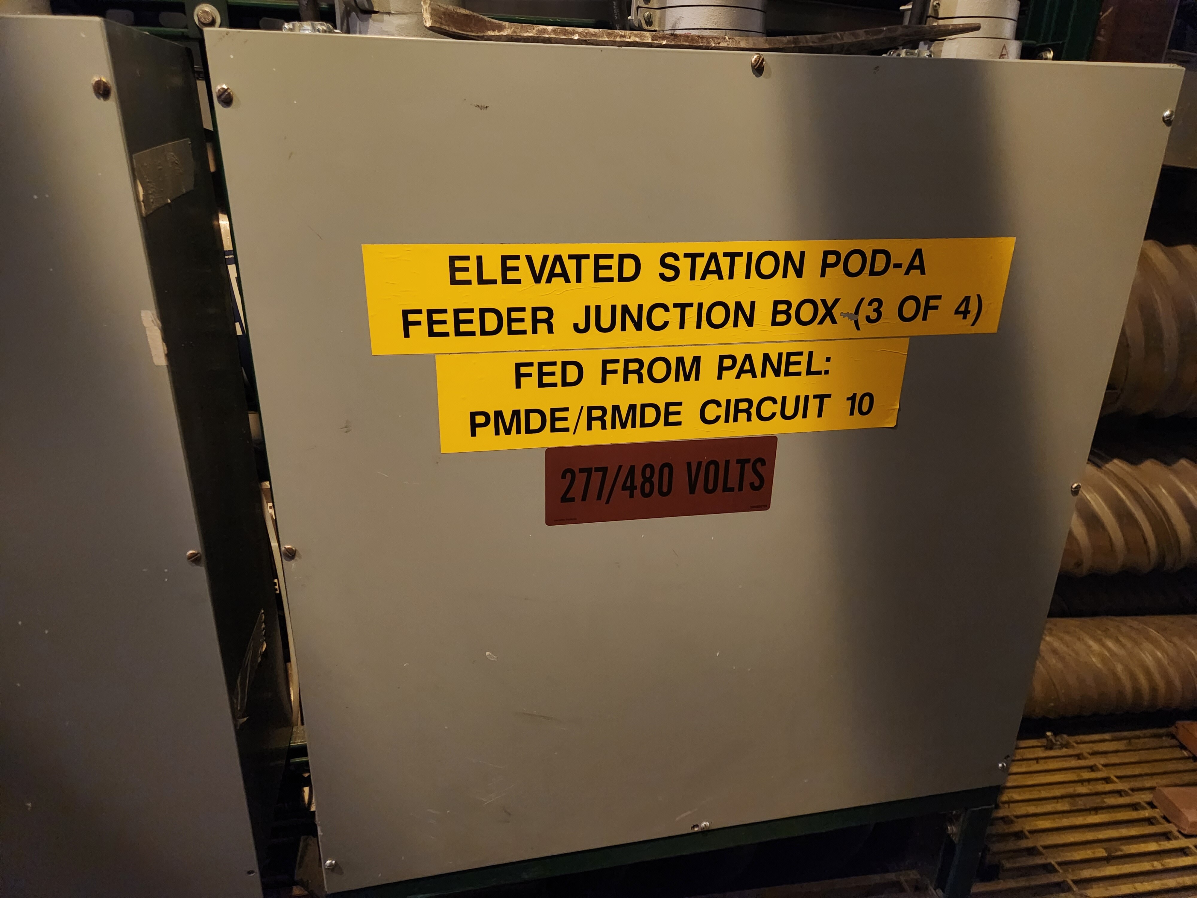
Power is routed from here, out across campus, to reasonable distribution points close to where it is used.
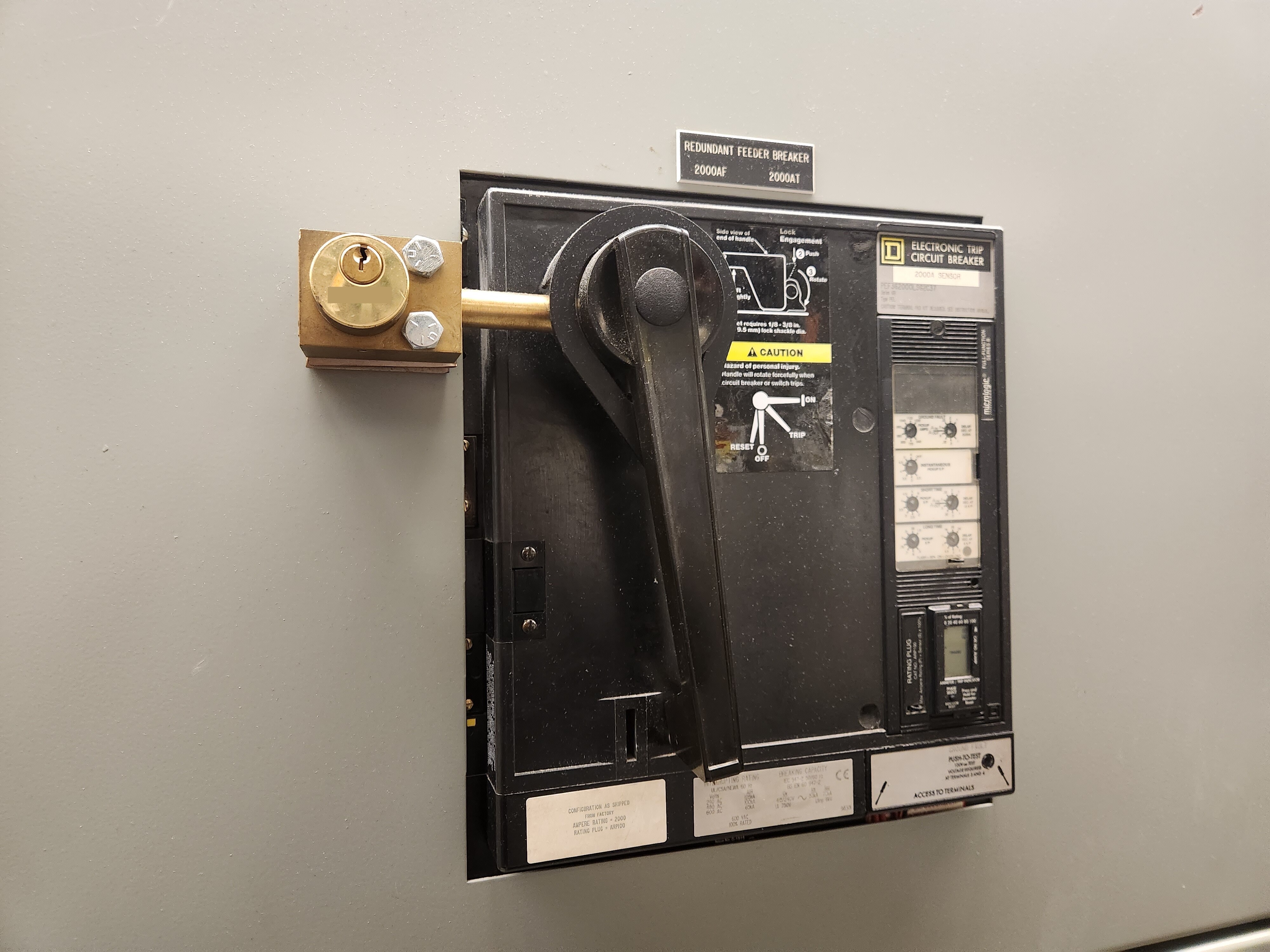
We also have a separate, redundant distribution panel. We can close a separate main breaker in order to route power to this redundant distribution panel, in the event of an issue with the primary distribution panel.
4,160 volt Distribution
I mentioned that there were a few exceptions to the 480-volt distribution network. We do have some outbuildings that are too far away from campus to effectively distribute power at 480 volts. For these locations, we step up to 4,160 volts. Distributing at a higher voltage means we require lower current to distribute the same amount of power. Lower current means less loss (voltage drop) for a given size wire, which allows us to feasibly distribute power to distant locations.
Here’s our 480 volt -> 4,160 volt transformer and our 4,160 volt switchgear. From here, power is routed to distant outbuildings.
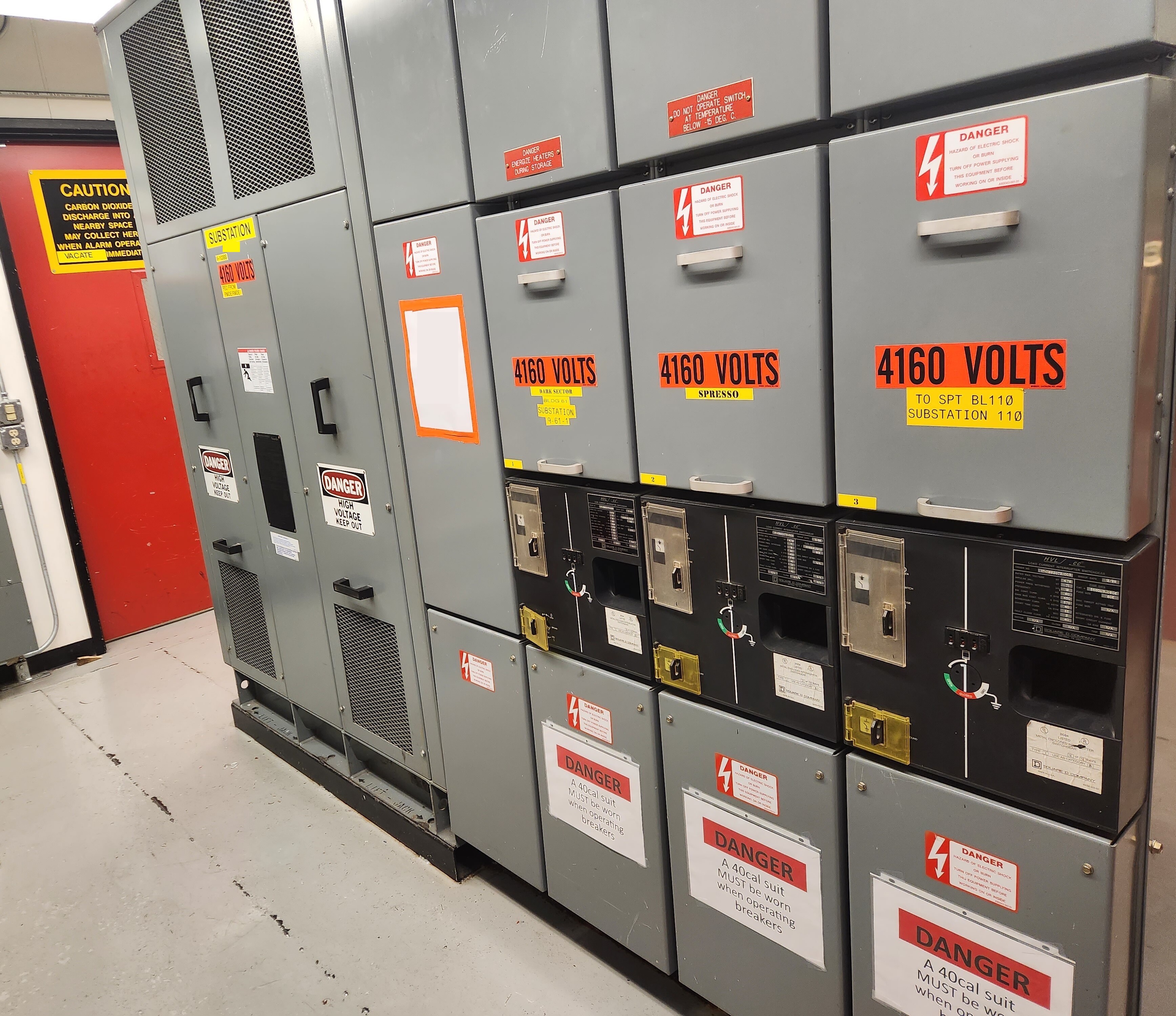
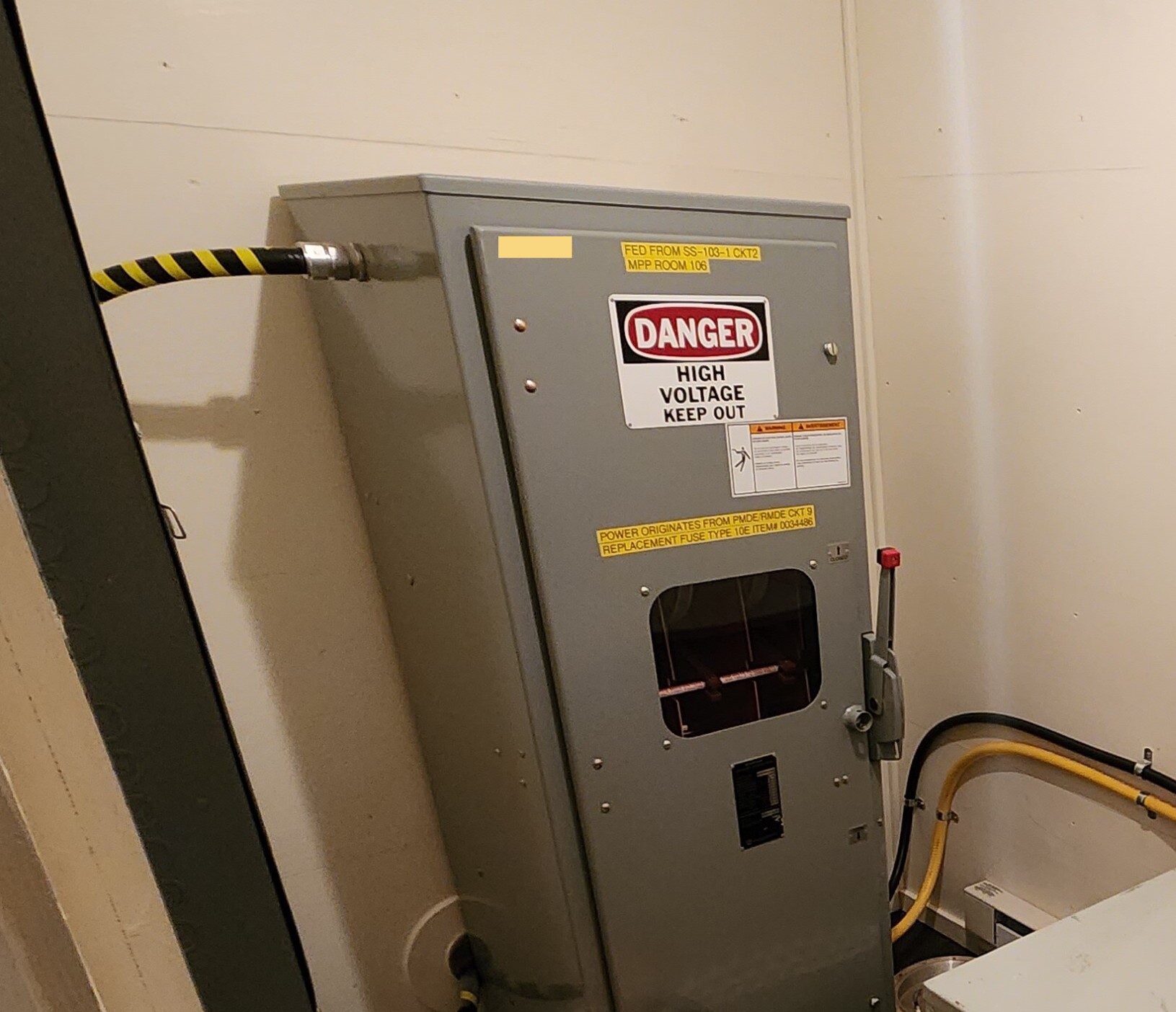
For example, the South Pole Remote Earth Science and Seismological Observatory (SPRESSO) vault sits about 5 miles away from our main South Pole campus. We distribute power to SPRESSO at 4,160 volts, which allows us to meet the power demand without using prohibitively-thick cables or being subject to excessive loss over this long distance.
At SPRESSO, we convert back to a reasonable voltage for the loads onsite. In this case it’s 208/120 volts.
Electrical Load Centers
As is typical for a campus this size, most large hardwired loads use 480/277 volts directly. This means the majority of lighting is 277 volts (phase to neutral), and most larger motors (HVAC, pumps, etc) are 480 volt, 3-phase.
3-phase 480/277-volt power means that the phase-to-phase voltage is 480 volts, and the phase-to-neutral voltage is 277 volts. Each phase consists of an AC sine wave that is 120 degrees offset from the next phase.
The math is beyond the scope of this post, but if you draw it all out, the formula for the phase-to-neutral voltage ends up being 480 volts / sqrt(3) = 277 volts.
Here’s an example of one of the primary distribution panels, which is where the 480/277 volt feed from the power plant is terminated. This is in our “B” Pod of the Elevated Station.
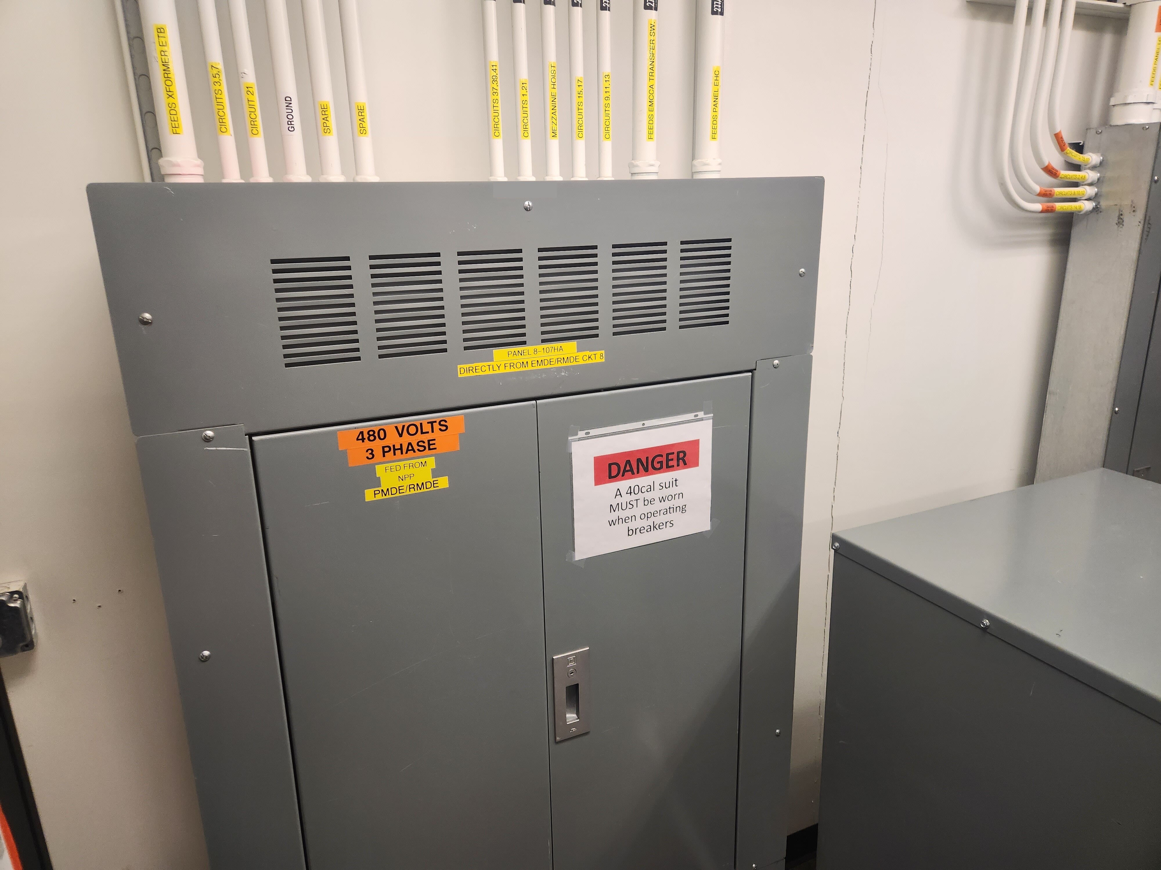
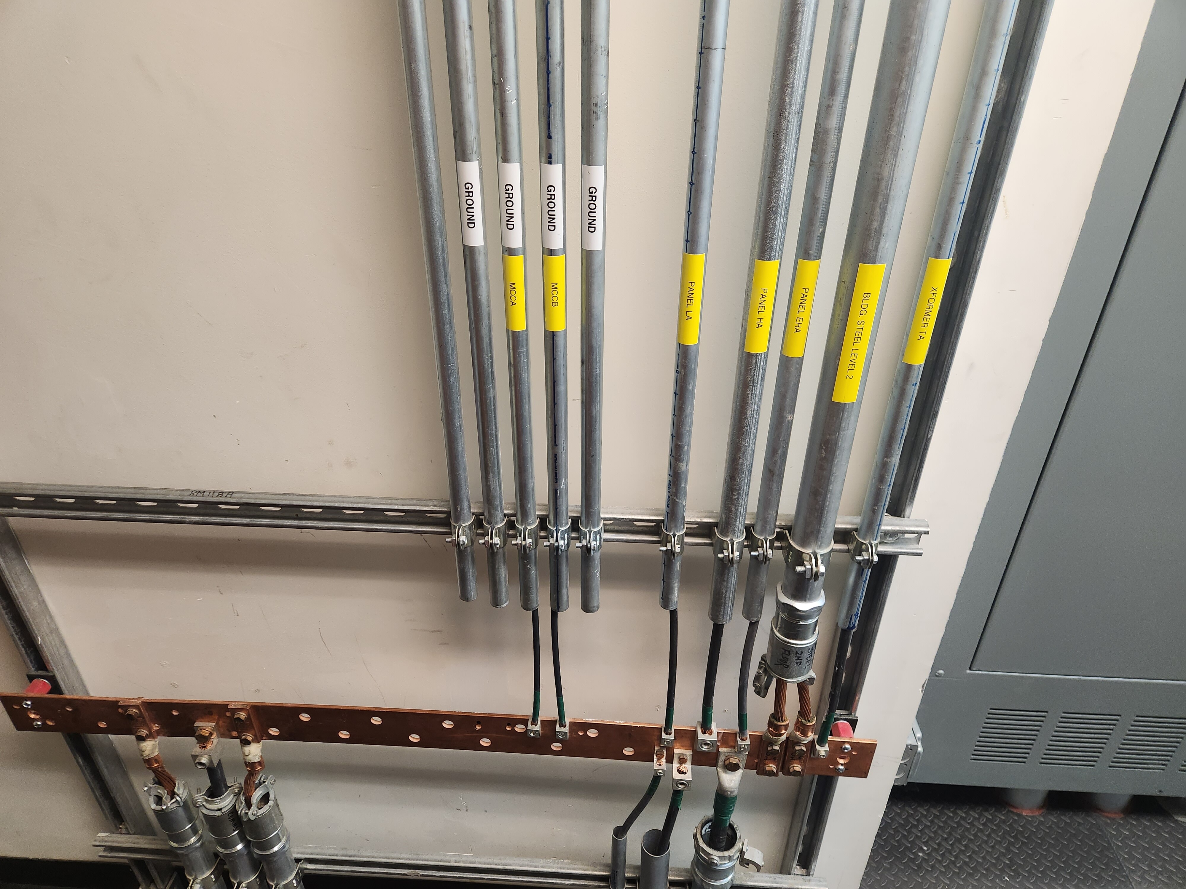
All grounds are aggregated on grounding bars located throughout campus. Safety grounds are extended to all electrical loads and metal surfaces, ensuring there is a redundant path for return current in the event of a fault.
480/277 Volt Loads
From here, power is routed to a number of 480/277 volt panels, serving major loads in this section of the building.
Major, fixed loads typically use 480/277 volts directly. It’s preferable to use power at the highest feasible voltage, with the fewest conversions possible from the source. Using 480/277 volt power directly means there is no conversion loss in transformers. We’re using the exact voltage that we generate in the power plant. It also means less current for the same amount of power, compared with 208/120 volts. Lower current means less loss in wires, which means we can use thinner wires.
For example, here’s one of our electric ovens in the galley kitchen. It is hardwired and runs directly on 480-volt, three-phase power. Typically loads like this consist of three separate heating elements, each across a different phase. So there are three, 480-volt elements inside, on phases A-B, B-C, and C-A. The total electrical draw of this entire oven unit peaks at 21.9 kilowatts, or just under ten times what can be delivered through a standard US commercial electrical outlet.

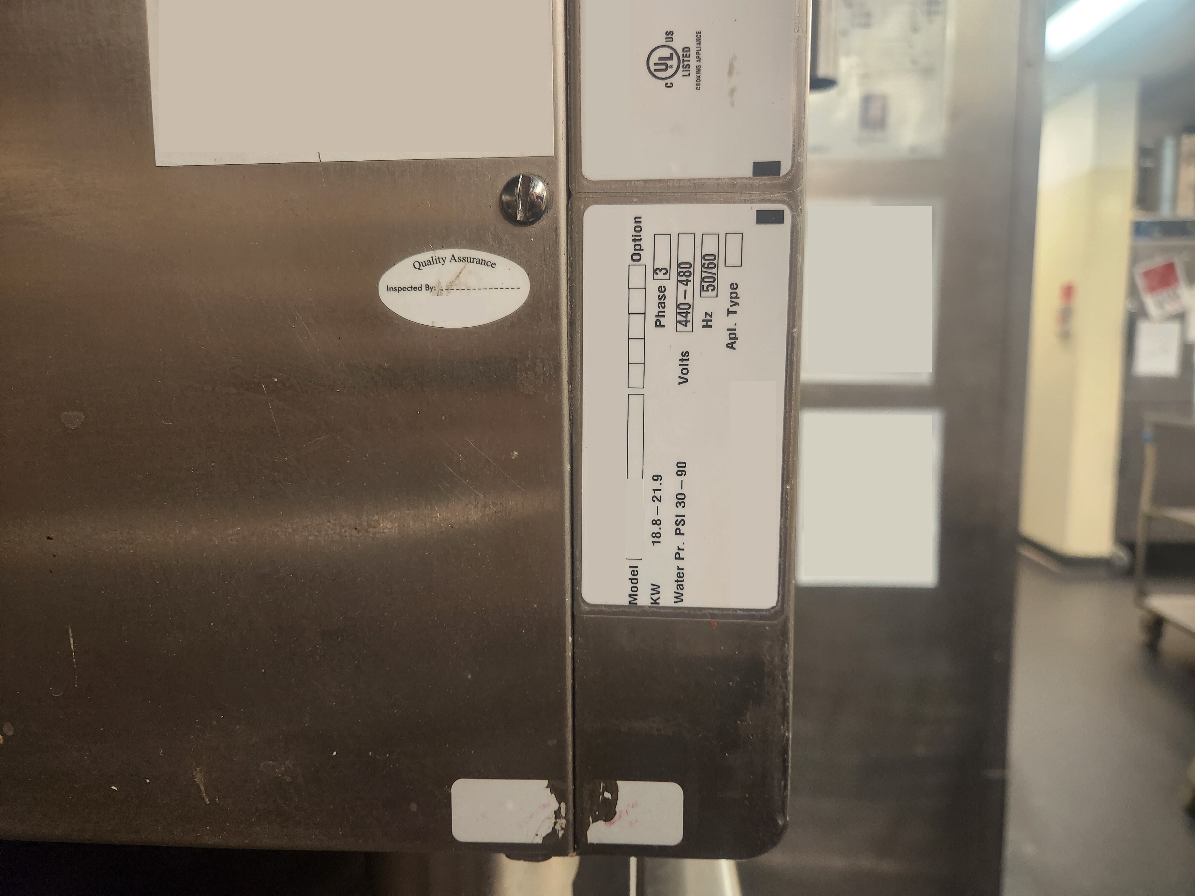
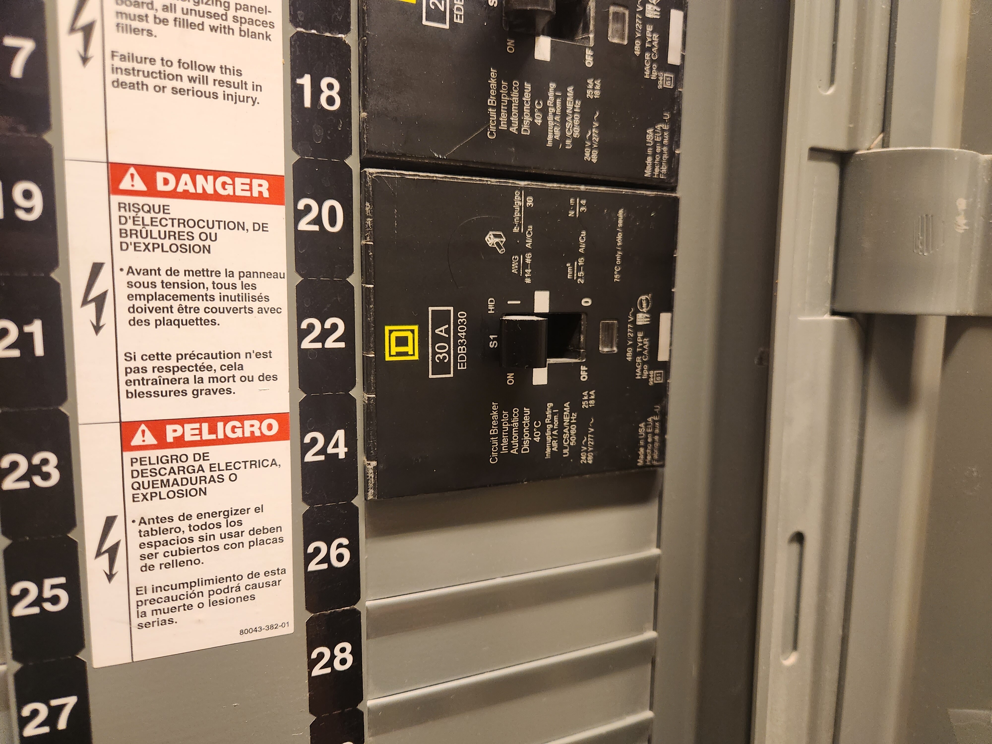
And here’s the corresponding breaker in one of our kitchen load panels:
Power for major motor loads is routed through a Motor Control Center. This is a panel that consists of control circuitry as well as Variable Frequency Drives (VFDs) to manage motor speeds.
A Variable Frequency Drive takes standard (i.e. 60hz) AC power in, and it outputs power at a lower, variable, controllable frequency, usually under the management of a software or other industrial control platform. For certain types of motors, where the motor speed is directly proportional to the frequency of the incoming power, this is a way to control the rotational speed of the motor. If the motor is driving, say, an HVAC blower, this allows us to precisely control the airflow in a given portion of the system.
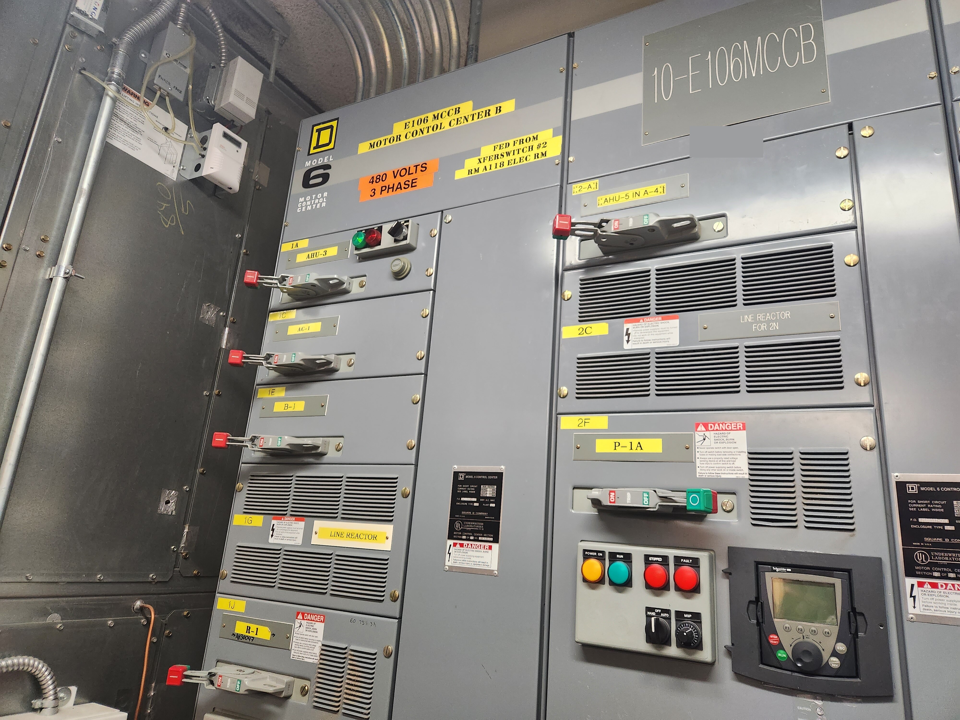
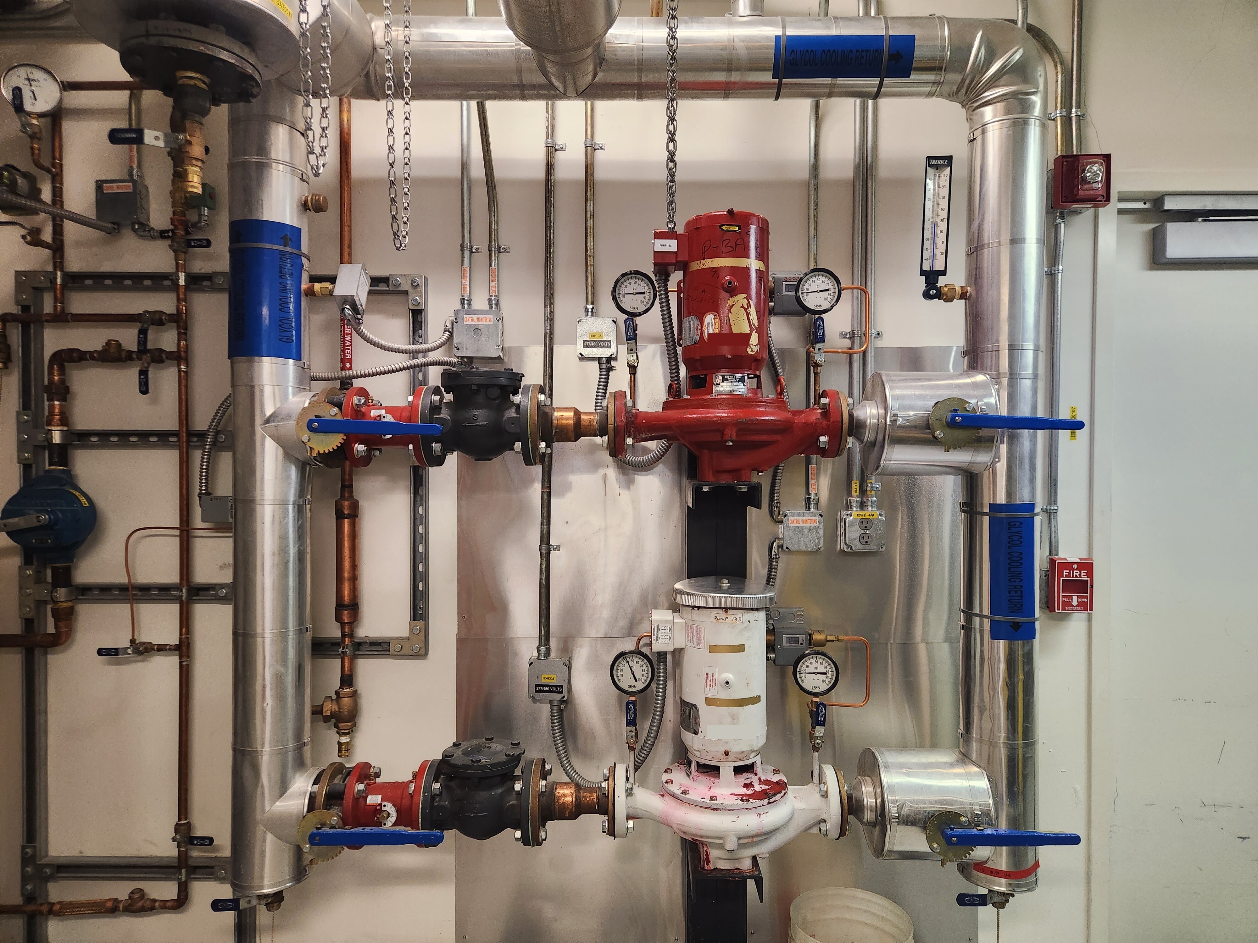
Motor Control Centers also contain controls for redundant motors. For example, on critical lines, there are often two pumps plumbed into the line. One is used at a time. The other one is in standby, and it can be automatically or manually started if the first one fails, or if it needs to be taken offline for maintenance.
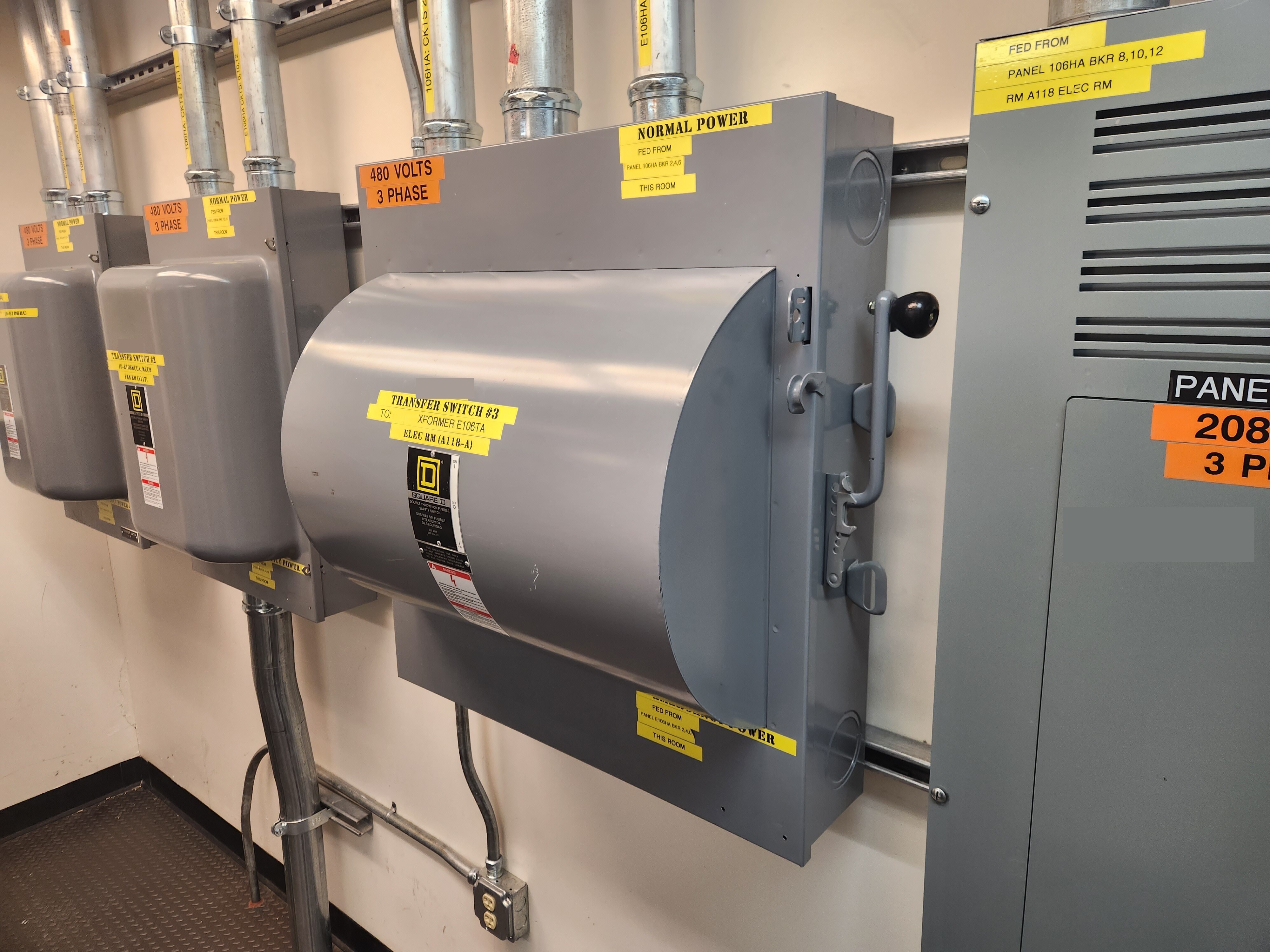
208/120 Volt Loads
We then step down to 208/120 volts, for smaller equipment and to serve plug loads. Here’s an example transformer used to accomplish this:
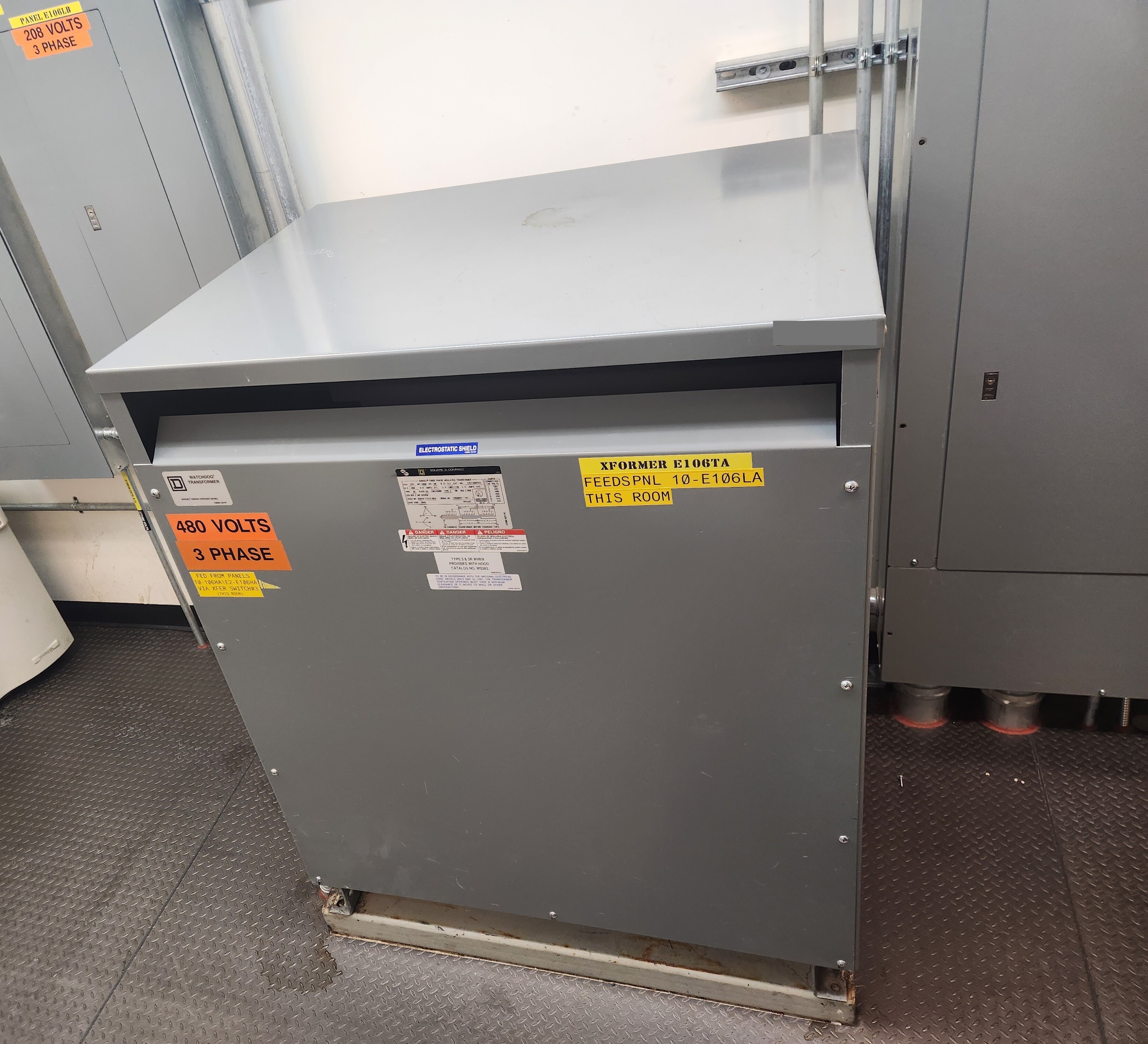
From here, 208/120 volt power is distributed to load panels.
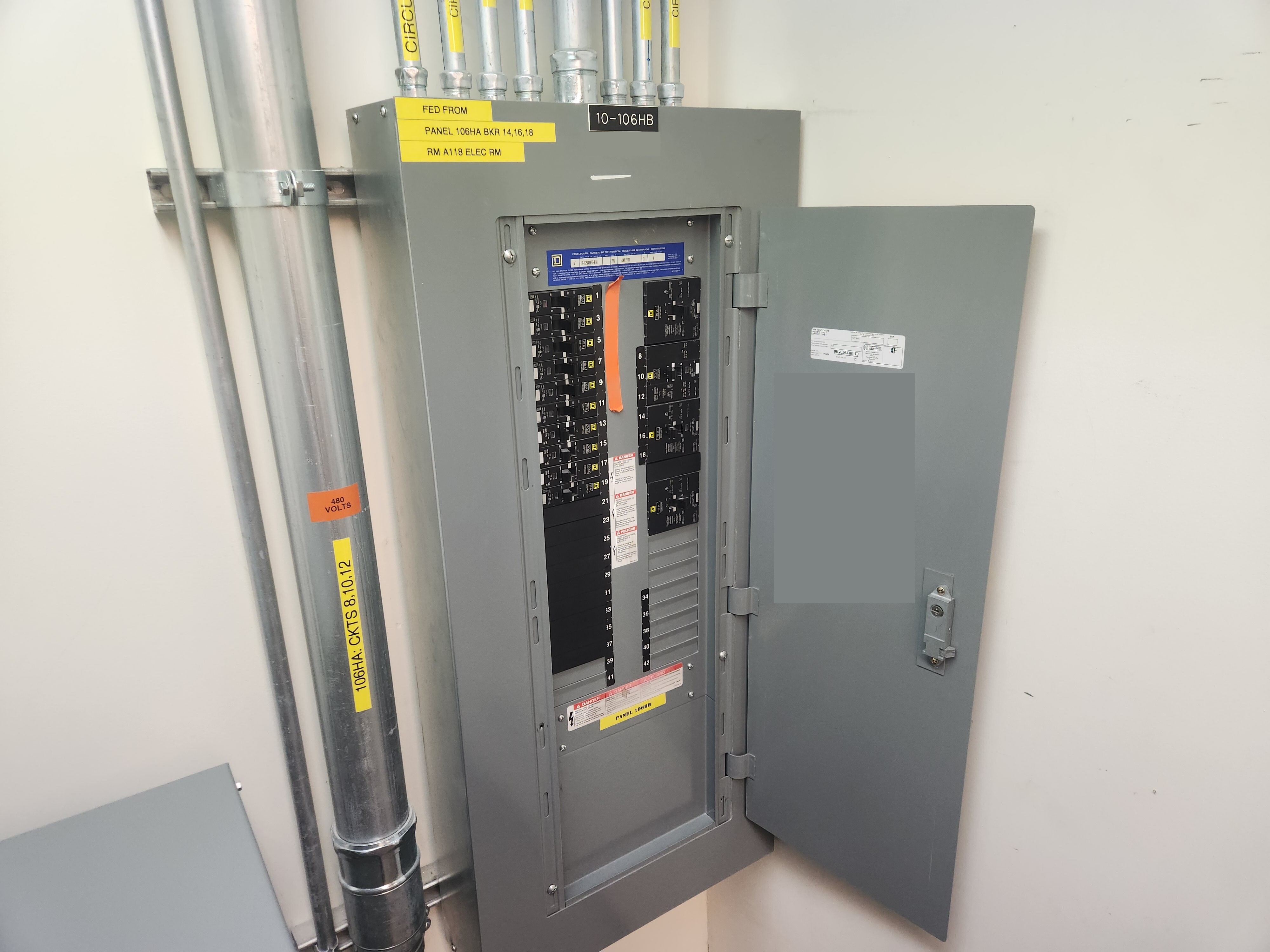
Here’s a standard 3-phase, 208/120-volt panel. You’ll note a combination of single-phase as well as three-phase breakers here. Standard electrical outlets make use of a single phase. They are 120 volt, phase-to-neutral. Some hardwired loads are 208-volt, 3-phase.
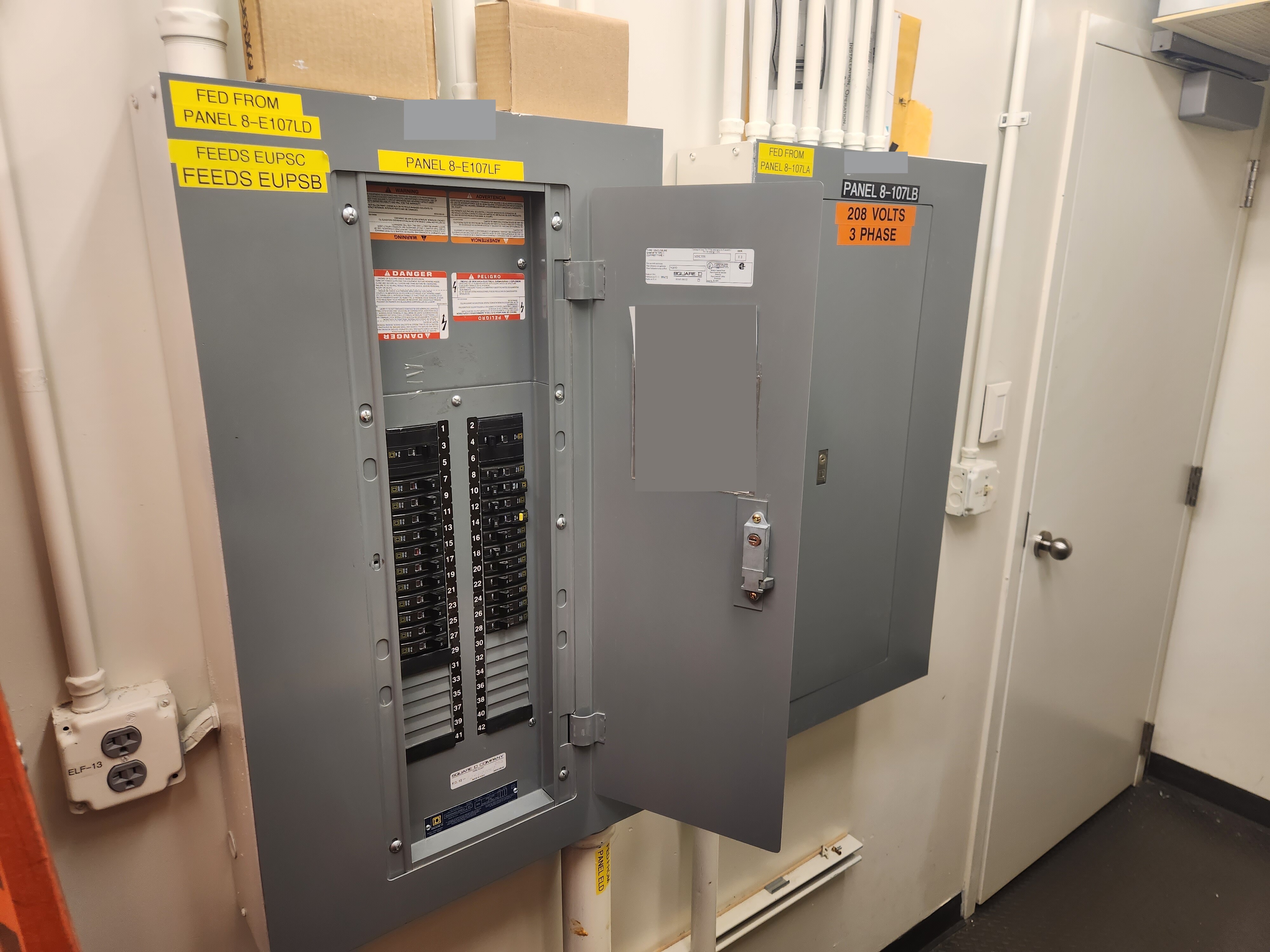
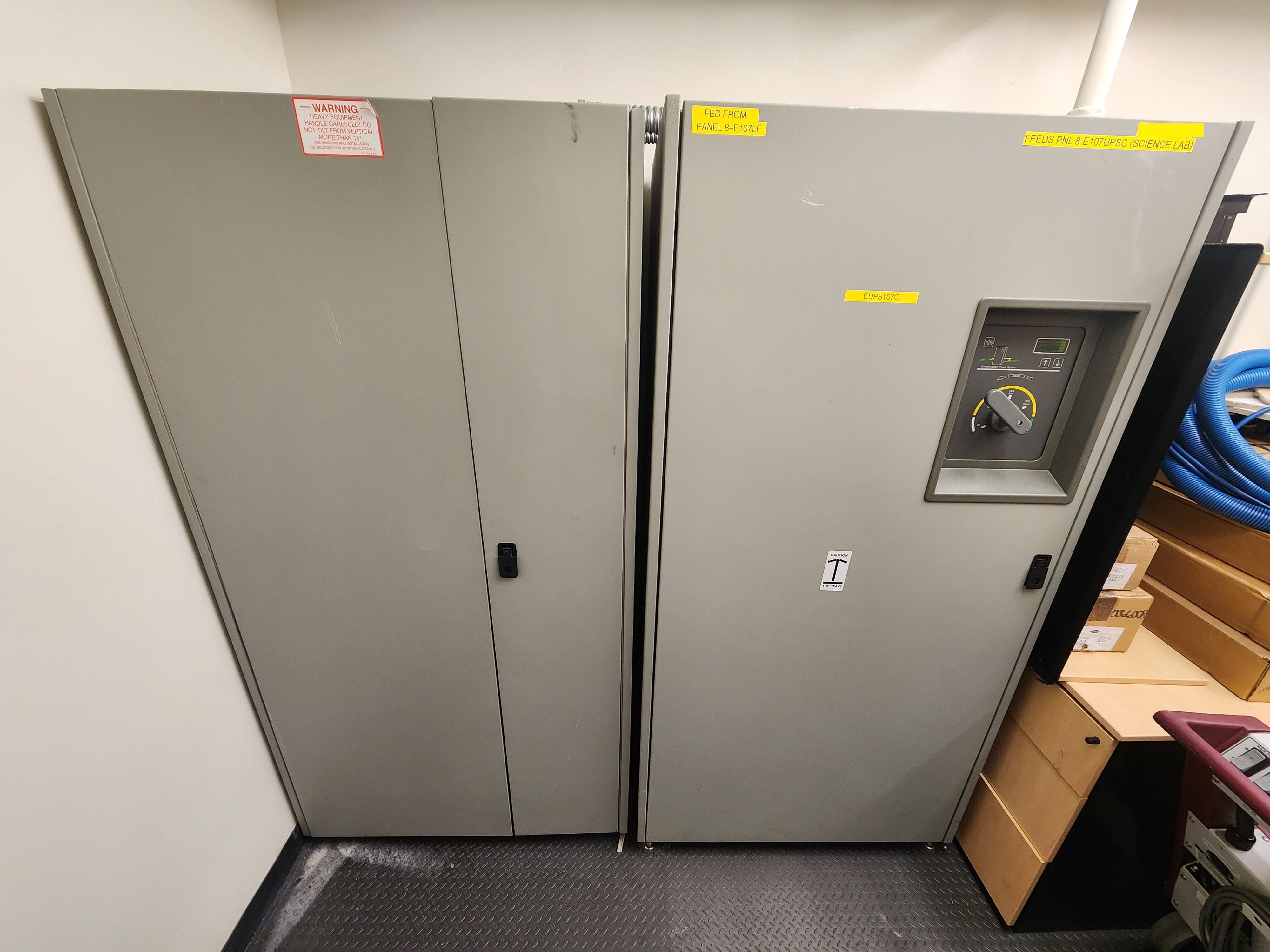
You’ll note that the panel in the above photo mentions that it feeds UPS units. Some of our critical loads, including certain science projects and operational equipment, are on large UPS units. These units consist of a large battery bank, plus an inverter.
During normal operation, the inverter is bypassed, and downstream loads are fed directly from station power. In the event that station power were lost or became unstable, the inverter would near-instantaneously kick on, drawing DC power from the batteries and supplying 208/120 volt, 3-phase AC power for the connected loads. When station power recovers, the bypass is restored, loads are once again served from station power, and the inverter is run in reverse to recharge the batteries.
The UPS units at Pole are connected to their own load panels, which serve critical outlets and hardwired loads throughout the station.
“Plug Load” refers to anything plugged into an electrical outlet. A standard commercial branch circuit in the United States consists of three wires. Two current-carrying conductors on a single phase (phase + neutral), plus a third wire operating as a non-current-carrying safety ground. These circuits are typically rated to carry up to 20 amps (16 amps continuous) at 120 volts. 20 amps at 120 volts is 2.4 kilowatts. These circuits typically contain NEMA 5-20R outlets.
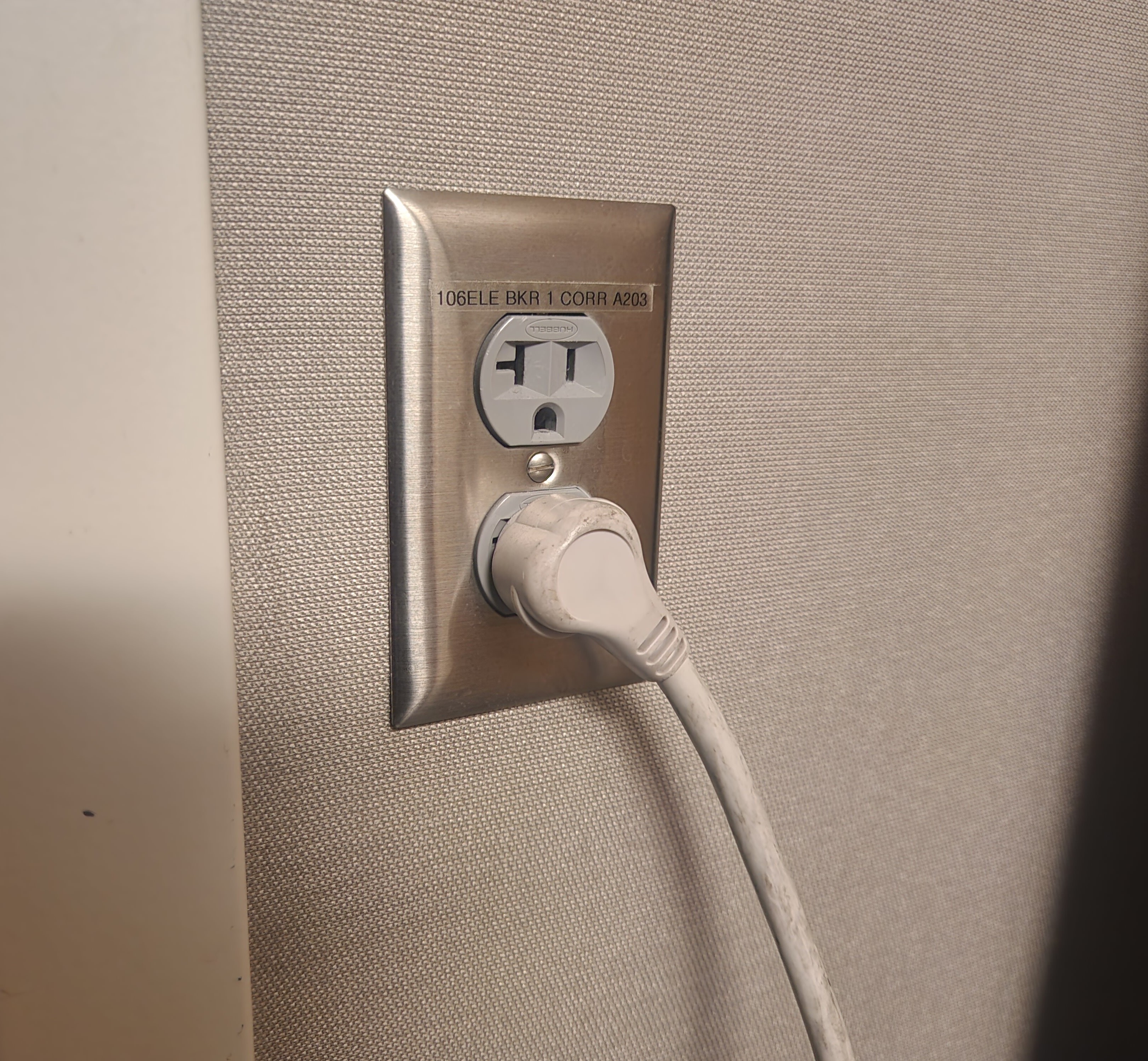
The phrase “plug load” is used to distinguish between these (relatively) small, variable loads, vs. fixed, hardwired loads such as pumps, compressors, blowers, lights, kitchen equipment, and other large, permanently-installed items.
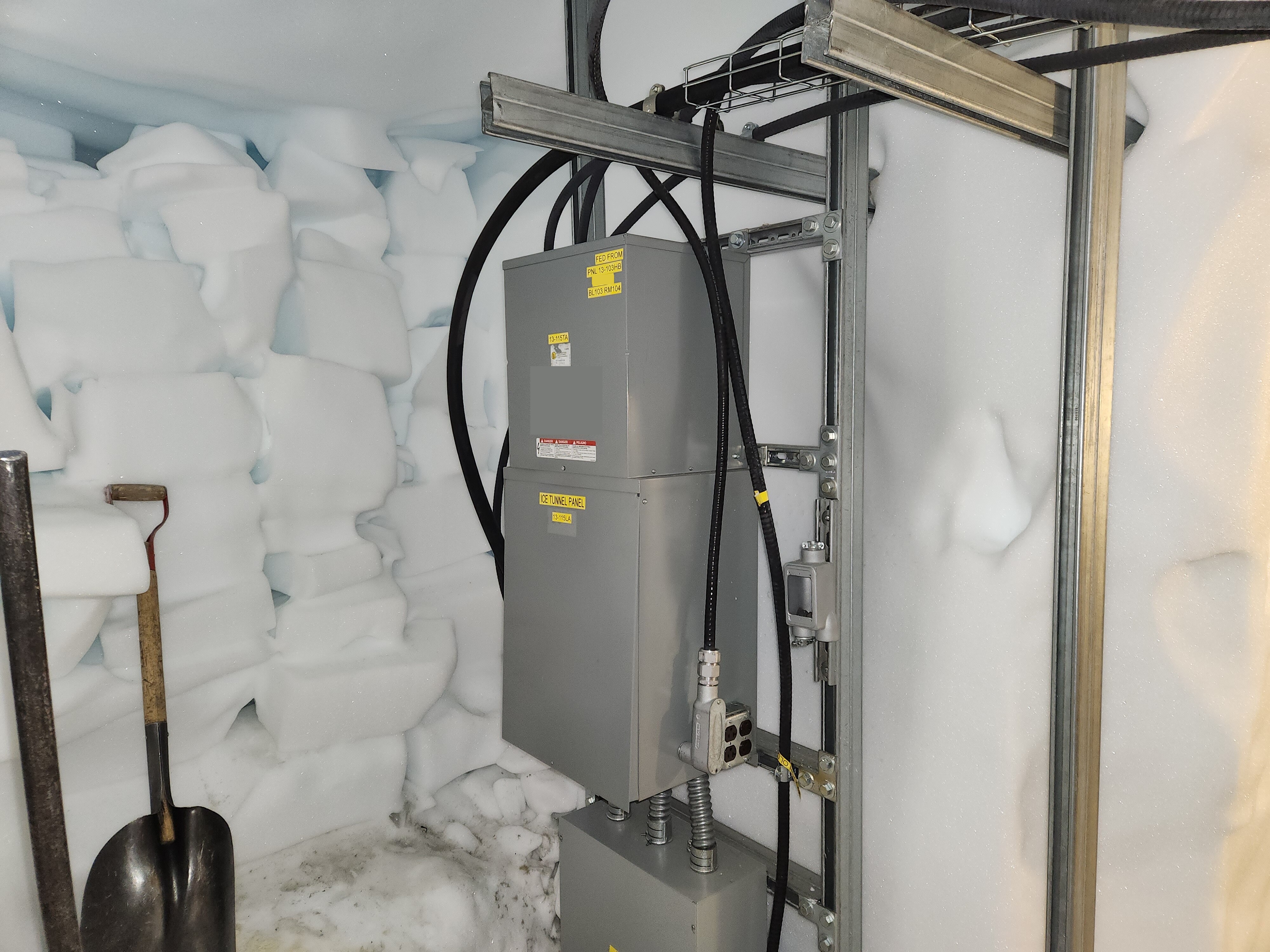
Power isn’t just needed in our warm, heated buildings! We also, of course, need power in unconditioned spaces. Probably the most extreme example is down in our ice tunnels. Here’s the transformer and panel that serves our lighting and outlets in the tunnels. This one is neat, because it’s really just anchored directly into the ice. Also it’s -55°F in here! Can you imagine working on this panel at -55°F?
Conclusion
And there you have it! Electrical generation, distribution, and consumption at the South Pole.
Really the only thing interesting about the electrical grid here is how uninteresting it is. The majority of what I’ve written here could apply to any commercial facility or small generating plant, anywhere in the United States.
The equipment itself, and the standards governing how it is all interconnected, is utterly unremarkable. It’s only interesting because of where it’s used, and the complex supply chain for keeping it all running, here at the bottom of the planet.
I hope others found this as interesting as I did.
Until next time!